Abstract: This paper introduces a wireless scheduling private network system, and designs the decision controller of the private network according to the performance index of the system, and gives the hardware structure of the decision controller.
Foreword The wireless dispatching private network is widely used in dispatching departments such as public security, railway, and taxi fleet. It is a mobile communication system mainly based on group calling, receiving and forwarding. The system generally works in different frequency duplex mode, which can realize voice communication between the dispatcher and each member of the mobile group (vertical), and between different members of the same group (horizontal). It is characterized by a small number of system channels and a small number of group users, requiring a small investment in network construction and a high network coverage rate. In the case of limited frequency resources, diversity reception, quasi-synchronous transmission wireless scheduling private network is the best solution to solve the problem of wide area coverage. The so-called diversity reception and quasi-synchronous transmission is the use of several co-frequency transmitting base stations to perform co-frequency and in-phase transmission on the downlink transmission signal of the system, covering the downlink communication area in all directions. At the same time, in order to solve the problem of relatively weak uplink signal of the mobile handheld station, M-1 co-frequency diversity receiving base stations can be added in areas with poor uplink communication, and each receiving base station cross-covers the uplink communication area of ​​the communication network. The selection control device of the system control center will analyze the M received signals for signal-to-noise ratio analysis, and instantaneously and dynamically switch the best received signal to the system for scheduling. This method is called "discriminatory diversity reception". Compared with the cluster scheduling network covered by the cell, it has the advantages of small system investment, less frequency resource occupation, and convenient operation and maintenance.
System composition and function The schematic diagram of this diversity receiving and quasi-synchronous transmission scheduling system is shown in Figure 1.
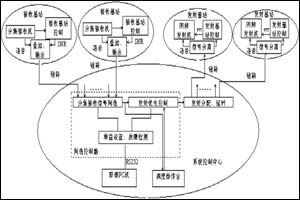
Figure 1 The selection controller of diversity receiving and quasi-synchronous transmission scheduling system is the core equipment of the system control center.
The composition and functions of the conventional wireless scheduling private network designed by ourselves are as follows: single channel, which can support up to 16 discriminant diversity receiving base stations and 4 quasi-synchronous transmitting base stations; the control center and the base station are connected by a wired link; the system is different Frequency duplex mode, mobile station is different frequency half duplex mode; co-frequency transmission uses rubidium oscillation source as the reference frequency; total system receive-forward delay ≤100ms; signal-to-noise ratio analysis and link static noise analysis; control center There are three dispatching consoles (one main dispatching console and two auxiliary dispatching consoles), which can monitor and dispatch; dispatchers can monitor the entire system through a friendly man-machine interface; the system has self-diagnostic functions, including receiving voice The quality of the link, the quality of the forwarding link, the automatic control of the gain of the system, etc. These functions need to be realized through the selection controller.
Among them, the signal-to-noise ratio analysis uses a combination of radio frequency selection (five levels of tones) and link static noise analysis. The radio frequency selection method is to analyze the signal-to-noise ratio of the system by judging the strength of each received radio frequency signal. It will "forward" most of the work that should have been carried out in the system control center on the noise analysis of the various voice signals to the receiving base station. This method is based on the fact that the stronger the high-frequency signal received by the receiver, the greater the squelch level of the receiver and the higher the signal-to-noise ratio of the voice signal output by the frequency discrimination. Therefore, at the receiving base station, the squelch level is subjected to detection, A / D conversion processing, and then it is divided into S levels, respectively corresponding to S specific levels of tones (frequency is outside the effective voice spectrum, see Table 1), and superimposed The received voice is transmitted back to the system control center via the link together. The selector in the control center simply compares the pitch frequency of the M channels of voice to select the best voice to ensure the shortest call access time.
Table 1 Correspondence table of high-frequency signal strength-squelch level-signal-to-noise ratio-level tone of a dispatching private network:
High frequency signal strength (50Ω)
Squelch level (600Ω)
Signal to noise ratio S / N
Grade tone
<0.3uV
0-10 dbm
<12db
2707hz
0.3-0.8uV
10-18 dbm
12-20db
2792hz
0.8-1.5 uV
18-25 dbm
20-28db
2852hz
1.5-2.2 uV
25-30 dbm
28-35db
2913hz
> 2.2 uV
> 30 dbm
> 35db
2972hz
Note: System voice frequency range 300-2500hz
System analysis and selection controller design The main function of this private network is actually to receive the information uploaded by the mobile station through the same frequency diversity receiving base station, and then forward it to the mobile station in the area through the same frequency transmitting base station, so as to realize the dispatching station and mobile Voice communication between each member of the group (vertical) and between different members of the same group (horizontal). In this process, multiple co-frequency transmitting base stations and multiple co-frequency diversity receiving base stations are involved. For voice signals, there is the problem of selecting the best channel. In order to make the entire system run reliably, it must have a self-detection function. These must be completed by a controller. Figure 2 is the functional composition of the selection controller.
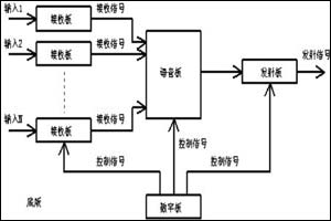
Figure 2 Functional block diagram of the selection controller From the analysis of the interface, the system requires 16 voice channels, 4 transmit signal channels, and 3 dispatcher signals and communication channels with the PC. Here at least 25 control signals are required, plus filters (separation of voice signals and specific level tone signals), self-test DTMF signals and A / D conversion and other controls. It is preliminarily determined that 40 control signals are required to have margin. Because the processing capacity of the system is not high, it can be realized by using ordinary single chip microcomputer. Judging from the current situation of single chip microcomputers on the market, the 51 series, PIC series and MSP series are more commonly used. Although the PIC and MSP series of single-chip microcomputers have more IO ports at the high end, the cost is considered higher. At the low end, their expansion is inconvenient. In terms of software programming, the instructions adopted by the PIC and MSP series are relatively simple, and it is relatively difficult to write some algorithms. The 51 series MCU has good versatility, strong expandability, and rich instructions. Although its speed is relatively slow, for the system's index of total receive-forward delay ≤100ms, it is also sufficient to use a 16MHz crystal (the instruction cycle is 0.8ms). Therefore, ATMEL's AT89C52 is used in the selection of the control chip.
In the specific implementation, there are two options to choose from. One is to use the 51 series chip's strong expansion capabilities, only one AT89C52 to complete the control of the entire system. Another considers the complexity of the system, can adopt the dual CPU structure, through the even distribution of the functions of the two CPUs, this will reduce the complexity of expansion and improve the system's responsiveness. Under normal circumstances, the monitoring system should try to use only one control chip solution. However, considering the complexity of the expansion and the complexity of the processing, it is appropriate for this system to adopt a dual CPU structure.
The control of the entire system uses a bus structure, that is, all voice signals are hung on the bus. After the control system analyzes and judges the uplink signal, the route with the best connection effect is connected, and then, the corresponding downlink and listening links are opened. In this way, using the bus structure makes the entire system simple and reliable. The CPU uses an interrupt to receive the access signal, which improves the system's ability to respond in time. In the interruption level, the dispatcher station has the highest level, followed by the access voice signal. Higher-level interrupts can mask lower-level interrupts and are interrupted by higher-level interrupts. Another key technology in the design is the design of the filter. The filter can be an active or passive filter. Considering that the low-pass filter requires a narrower transition band (the system voice frequency range is 300-2500 Hz, and the lowest level of tone is 2707 Hz), if a passive filter is used, Very high debugging skills. Therefore, an active 8th-order EllipTIc 2.5KHz low-pass filter (implemented with LTC1064) is used.
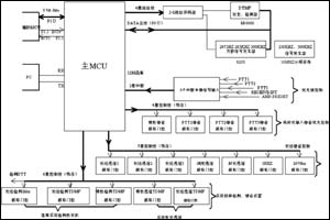
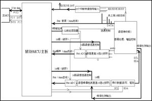
The realization of the controller is divided into two parts: hardware and software. The hardware mainly includes two parts: audio signal and follow-up control signal processing function module, MCU control and monitoring function module. The audio receiving plug-in module will receive the received audio signal (frequency range: 100Hz-2500Hz) and the accompanying receiving control signal (single tone sine wave, frequency range: 2700Hz-3000Hz, which is generated by the base receiving station equipment and superimposed on the audio signal , Stands for the size of the signal-to-noise ratio S / N0 of the audio signal received by the base station) and is separated after band-pass amplification, and the audio signal is amplified to ─10dBmw / 600Ω and output; the frequency-data (FD) conversion of the received control signal along with Output a parallel 4bit DATA data (hang on auxiliary MCU data bus). According to the instructions of the main MCU, the audio transmission plug-in module will select the three audio signals such as the MIC audio signal, the (best) received voice signal to be forwarded, and the self-test DTMF signal to select one, and then superimpose it on the channel. Control signal (2972Hz single-tone sine wave), and amplify and distribute it into three outputs (0dBmw / 600Ω). The main MCU control module includes 89C52 single chip microcomputer (main), I / O port address decoder circuit, receive / transmit voice channel strobe, latch circuit, hardware watchdog circuit (hardware automatically resets when the system crashes), DTMF signal Detection / generation function module, along with the transmission signal (2972HZ) generation circuit, external interrupt source expansion circuit, MCU and PC communication using RS-232 serial communication circuit, the rate is 9600bit / s, duplex communication mode. Voice judgment control module includes 89C52 single-chip (auxiliary), external circuit, I / O address decoder circuit, 8-bit parallel data port drive circuit, 16-channel receive voice channel strobe, latch circuit, voice channel static noise analysis Circuit, hardware watchdog circuit (hardware is automatically reset when the system crashes). The system voice / control signal interface module superimposes the three channels of MIC voice sent from three dispatching operation consoles (one main dispatching operation console and two auxiliary dispatching operation consoles) according to priority, and superimposes with the received voice, and sends it to the recording output ( Two) interfaces; send the received voice to the three dispatching consoles for monitoring; send the priority dispatched voice and the received voice to the audio transmission module respectively; send the control signals (transmit control signal PTT and receive voice forwarding) sent by the dispatch console The control signal T / T) is sent to the main MCU. Figure 3 and Figure 4 are the hardware block diagram of the main and auxiliary MCU of the controller.
The software of the system includes: control main program (main MCU) and judgment program (auxiliary MCU). The software flow can be obtained from the hardware design.
Conclusion The private network system of a unit in Guangzhou was established in the early 1980s. The system is imported equipment, which is now relatively old and has insufficient functions. In order to improve system security and facilitate system maintenance, we developed this system. This system has been greatly improved compared to the old system, mainly expanding the transmitting base station and receiving base station of the system. The old system has only one transmitting base station and eight receiving base stations. The current system can support up to 16 discriminant diversity reception Base station, 4 quasi-synchronous transmitting base stations; automatic gain control of the system; the method of combining signal-to-noise ratio analysis and link static noise analysis in channel judgment, which is better than only using signal-to-noise ratio analysis and judgment; system self-diagnosis function; system Modular structure improvement. The development of the system realizes the localization of the dedicated network monitoring system, improves the safety and maintainability of the system, and has very good economic and social benefits.
Figure 3 Main MCU control module Figure 4 Auxiliary MCU control module
references:
1. Ma Jian, Practical Technology of Trunking Mobile Communication, People's Posts and Telecommunications Press, 1996

Follow WeChat

Download Audiophile APP

Follow the audiophile class
related suggestion
The design of tilt sensor based on PIC microcontroller introduces the working principle of tilt sensor, connects the hardware of PIC16C72 and tilt sensor ...
Abstract: Explain the function and implementation structure of Cypress's configurable system on chip (PSoC); combined with the development of color selection controller ...
'+ data.data.username +' '; dom + ='
[Super bright with multiple modes]Multi-functional Lights generates a brilliant large area floodlight or a perfect focused spotlight. Adjustable focus with 3 or 5 modes.
[High quality]The Multi-Functional Lights body is designed by high quality ABS, and it has a very solid construction,High-Efficiency and Great Output LED Chip.
[Easy to carry and charge]Easy to carry as a backup tool and small enough to put in your pocket, handbag, drawer, or car compartment. The Multi-functional Lights take standard AAA/AA or 18650 rechargeable battery.
[Waterproof and Shockproof]Anti-slip handle designing,make this flashlight perfect for using in the rain, snow or other emergency situations. It also can be used in wet condition or light rain day
Multi-functional Lights
Multi Tool With Flashlight,Leatherman Flashlight,Multi-Functional Lights,Multi Tool With Light
Ningbo Henglang Import & Export Co.,Ltd , https://www.odistarflashlight.com