Application of WPAN network configuration based on ZigBee
ZigBee is an emerging wireless network technology with short distance, low speed, low cost and low power consumption. It uses direct sequence spread spectrum (DSSS) technology, and the operating frequency is 868MHz, 915MHz or 2.4GHz, which is a frequency that does not require a license. The configuration of wireless personal area network based on ZigBee technology is a new development of short-range wireless communication technology in recent years, and it has been more and more widely used in the field of industrial automation and smart home.
ZigBee network configuration
1 Composition of network equipment
ZigBee network equipment mainly includes network coordinator, full-function equipment and reduced-function equipment.
â‘ The network coordinator contains all network messages. It is the most complex of the three types of devices, with the largest storage capacity and the strongest computing power. The function is to send network beacons, build a network, manage network nodes, store network node information, find routing messages between a pair of nodes, and continuously receive information.
â‘¡ Full-Functional Device (Full-FuncTIon Device, FFD) can act as a network coordinator to form a network and allow other FFD or reduced-function devices (RFD) to connect. FFD has the function of a controller and can provide two-way transmission of information. The device characteristics are as follows.
â— With all IEEE 802.15.4 functions and all features specified by the standard;
â— Stronger storage and computing power can make it function as a network router when idle;
â— Can also be used as a terminal device.
â‘¢ Reduced-function device Reduced-function device (Reduced-FuncTIon Device, RFD) can only transmit information to or receive information from FFD, and its device characteristics are as follows.
â— With limited functions to control cost and complexity;
â— Usually used as terminal equipment in the network;
â— RFD reduces the cost of ZigBee components because it saves memory and other circuits, and a simple 8-bit processor and small protocol stack also help reduce costs.
2 Network node types From the network configuration, there are three types of nodes in the ZigBee network: ZigBee coordination point, ZigBee routing node and ZigBee terminal node.
â‘ ZigBee coordination point
ZigBee coordination point is also called PAN (Personal Area Network) coordination point (ZigBee Coordinator, ZC) in IEEE 802.15.4, and can be used as a convergence node in wireless sensor networks. The ZigBee coordination point must be FFD. A ZigBee network has only one ZigBee coordination point. It is often more powerful than other nodes in the network and is the master node of the entire network. It is responsible for initiating the establishment of a new network, setting network parameters, managing nodes in the network, and storing node information in the network. After the network is formed, it can also perform the function of a router. The ZigBee coordination point is the most complex of the three types of ZigBee nodes, which are generally continuously powered by AC power.
â‘¡ ZigBee routing node
The ZigBee router node (ZigBee Router, ZR) must also be FFD. ZigBee routing nodes can participate in route discovery, message forwarding, and extend network coverage by connecting other nodes. In addition, the ZigBee routing node can also act as a common coordination point (IEEE 802.15.4 is called a coordination point) in its personal operation space (POS, Personal OperaTIng Space). The common coordination point is different from the ZigBee coordination point, it is still controlled by the ZigBee coordination point.
â‘¢ ZigBee terminal node
ZigBee end node (ZigBee EndDevice, ZE) can be FFD or RFD, it is connected to the network through ZigBee protocol or ZigBee routing node, but no other nodes are allowed to join the network through it. .
3 Network working mode
The working mode of ZigBee network can be divided into beacon (Non-beacon) and non-beacon (Non-beacon) modes. The beacon mode realizes the synchronous work and synchronous sleep of all devices in the network to achieve maximum power saving The non-beacon mode only allows ZE to sleep periodically, and ZC and all ZR devices must be in working condition for a long time.
In beacon mode, ZC is responsible for broadcasting beacon frames to the network at certain intervals (generally between 15ms and 4min). There are 16 identical time slots between two beacon frames. These time slots are divided into network sleep zones And the two parts of the network active area, the message can only be sent in each time slot of the network active area.
In the non-beacon mode, the ZigBee standard adopts a parent node as the ZE child node to cache data, and ZE actively extracts data from its parent node to realize the periodic (period can be set) sleep of ZE. All parent nodes in the network need to cache data frames for their ZE child nodes. All ZE child nodes are in sleep mode most of the time. Wake up periodically to shake hands with the parent node to confirm that they are still in the network. It usually only takes 15ms to switch to data transmission mode.
Network Topology
The IEEE 802.15.4 network can be organized into a star network or a point-to-point network according to the needs of the application. In a star structure, all devices communicate with the central device PAN network coordinator. In such a network, the network coordinator generally uses a continuous power system to supply power, while other devices use battery power. The star network is suitable for small-scale indoor applications such as home automation, personal computer peripherals, and personal health care. Unlike the star network, as long as the peer-to-peer network is within the wireless range of each other, any two devices can communicate directly. A peer-to-peer network also needs a network coordinator, which is responsible for managing link state information and authenticating device identities. The point-to-point network mode can support Ad Hoc networks, allowing data to be transmitted in the network through multi-hop routing. However, it is generally believed that the problem of self-organization is solved by the network layer, which is not within the scope of the IEEE 802.15.4 standard. The point-to-point network can construct a more complex network structure, which is suitable for applications with a wide range of equipment distribution. For example, it has a very good application background in industrial inspection and control, cargo inventory tracking and intelligent agriculture.
Because the tree network and the mesh network have the function of routing data packets between multiple networks, they are called multi-hop networks, and star networks are called single-hop networks. Like any network, the ZigBee network is also a multi-point access network, which means that all nodes in the network have equal access to the communication medium. There are 2 types of multi-point access mechanisms. In a network without beacon enabled, as long as the channel is idle, all nodes are allowed to send at any time. In a beacon-enabled network, only nodes are allowed to transmit in predefined time slots. The coordinator will periodically start sending with a super frame identified as a beacon frame, and hope all nodes in the network synchronize with this frame. In this super frame, each node is assigned a specific time slot, in which the node is allowed to send and receive data. The super frame may also contain a common time slot. At this time, all nodes in the slot compete for access to the channel.
Although the formation process of the network topology is a function of the network layer, IEEE 802.15.4 provides sufficient support for forming various network topologies. When planning and designing, usually need to consider the network capacity and delay. Although the network capacity of the ZigBee standard can support up to 65535 network nodes, it takes 15ms to complete communication for every two adjacent nodes, so in practical applications, network coverage and response time need to be considered. The single-point capacity is large, and the coverage is not expanded; the response time is large, and the application service cannot be realized. This requires designing an effective network topology combination to meet various applications according to different application environments.
1 Star network Star network is a radial system, data and network commands are transmitted through the central node. In this routing topology, peripheral nodes need to be directly connected to the central node wirelessly. The conflict or failure of a certain node will reduce the reliability of the system. The biggest advantage of the star network topology is the simple structure, because there are few upper-layer protocols to be implemented, the cost of the equipment is low, and there is less upper-layer routing management; the central node undertakes most of the management work, such as issuing certificates and remote gateway management. . The disadvantage is that the flexibility is poor, because each terminal node needs to be placed in the communication range of the central node, which will inevitably limit the coverage of the wireless network; moreover, centralized information flows to the central node, which easily causes network congestion, packet loss, and performance Decline and other situations.
The star network is centered on the network coordinator, and all devices can only communicate with the network coordinator. Therefore, in the formation of the star network, the first step is to establish a network coordinator. Any FFD device may become a network coordinator. How a network determines its own network coordinator is determined by the upper layer protocol. A simple application strategy is that after an FFD device is activated for the first time, it first broadcasts a request to query the network coordinator. If a response is received indicating that a network coordinator already exists in the network, then through a series of authentication processes, the device It has become an ordinary device in this network. If no response is received, or the authentication process is unsuccessful, the FFD device can establish its own network and become the network coordinator of the network. Of course, there are some more in-depth problems here. One is the network coordinator expiration problem, such as the original network coordinator is damaged or energy is exhausted; the other is the accidental factors that cause multiple network coordinator competition problems, such as moving object blocking This causes an FFD to establish its own network. When a moving object leaves, multiple coordinators will appear in the network.
The network coordinator must choose a unique identifier for the network. All the devices in the star network use this identifier to specify their own ownership. Devices between different star networks communicate with each other by setting up special gateways. After selecting an identifier, the network coordinator allows other devices to join its own network and forward data packets for these devices. If two devices in a star network need to communicate with each other, they first send their respective data packets to the network coordinator, and then the network coordinator forwards them to each other.
2 Tree Network A tree network is an example of a point-to-point network, and is also a typical network topology of ZigBee. In a general point-to-point network, any two devices can communicate directly as long as they can receive each other's wireless signals, without the need for other devices to forward them. However, a peer-to-peer network still needs a network coordinator, but the function of the coordinator is no longer to forward data for other devices, but to complete basic network management functions such as device registration and access control. The generation of the network coordinator is also stipulated by the upper layer protocol. For example, the first device to start communication on a certain channel is used as the network protocol device on the channel.
In ZigBee's tree-like network, most devices are FFD devices, and RFD devices are always connected to the network as tree-like leaf devices. Any FFD can act as an RFD coordinator or network coordinator, providing synchronization information for other devices. Among these coordinators, only one can act as a network coordinator for the entire point-to-point network. The network coordinator may be the same as other devices in the network, or it may have more computing resources and energy resources than other devices. The network coordinator first sets itself as a cluster head (Cluster Header, CLH), sets the cluster identifier (Cluster IdenTIfier, CID) to 0, and selects an unused PAN network identifier for the cluster to form a network The first cluster. Then, the network coordinator starts broadcasting beacon frames; neighboring devices can apply to join the cluster after receiving the beacon frames; whether the device can become a cluster member is determined by the network coordinator. If the request is allowed, the device will join the cluster coordinator's neighbor list as a child of the cluster. The newly added device will add the cluster head as its parent device to its neighbor list.
The above description is just the simplest tree formed by a single cluster. The personal area network coordinator can designate another device as the adjacent new cluster head to form more clusters. The new cluster head can also choose other devices as cluster heads to further expand the coverage of the network. However, too many cluster heads will increase the delay of message transfer between clusters and communication overhead. In order to reduce the delay and communication overhead, the cluster head can select the farthest communication device as the cluster head of the adjacent cluster, which can minimize the number of hops for message transfer between different clusters and achieve the purpose of reducing delay and overhead.
3 Mesh network
The MESH mesh network topology structure has powerful functions. The network can communicate through "multi-level hopping"; the topology structure can also form an extremely complex network; the network also has self-organizing and self-healing functions.
Mesh (Mesh) network is a special, point-to-point network structure transmitted in relay mode, and its routes can be automatically established and maintained. It can be seen from Figure 1 that a ZigBee network has only one network coordinator, but there can be several routers. The coordinator is responsible for building the entire network, and it can also serve as a communication node (gateway) with other types of networks. The devices that make up the coordinator and router must be full-function devices (FFD), and the devices that make up the terminal device can be full-function devices or simple-function devices (RFD).
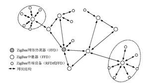
Figure 1 ZigBee mesh network structure diagram
Node functions and configuration files
1 Node function A typical ZigBee node can support a variety of features and functions. For example, an I / O node may have multiple digital and analog inputs / outputs. Some digital inputs may be used by one remote controller node, while other digital inputs may be used by another remote controller node. This distribution will create a truly distributed control network. In order to facilitate data transmission between the I / O node and the two controller nodes, the application programs in all nodes must save multiple data links. To reduce costs, ZigBee nodes use only one wireless channel to create multiple virtual links or channels with multiple endpoints / interfaces.
A ZigBee node supports 32 endpoints (numbered 0 to 31) and 8 interfaces (numbered 0 to 7). Endpoint 0 is reserved for device configuration, while endpoint 31 is reserved for broadcasting only, and a total of 30 remaining endpoints are used for applications. Each endpoint has a total of 8 interfaces. Therefore, in practice, there may be up to 240 virtual channels in a physical channel.
A typical ZigBee node will also have many attributes. For example, an I / O node contains attributes called digital input 1, digital input 2, analog input 1, and so on. Each attribute has its own value. For example, the numeric input 1 attribute may have a value of 1 or 0. The collection of attributes is called a cluster. In the entire network, each cluster is assigned a unique cluster ID, and each cluster has a maximum of 65535 attributes.
2 Configuration file
The ZigBee protocol also defines a term called a configuration file. A configuration file is a description of a distributed application. It describes distributed applications based on the data packets that the application must process and the operations that must be performed. The descriptor is used to describe the configuration file, and the descriptor is just a complex structure of various values. This configuration file makes ZigBee devices interoperable. The ZigBee Alliance has defined many standard configuration files, for example, remote control switch configuration files and light sensor configuration files. Any node that follows a standard configuration file can interoperate with other nodes that implement the same configuration file. Each configuration file can define up to 256 clusters, and each cluster can have up to 65535 attributes. This flexibility allows nodes to have a large number of attributes (or I / O points).
Conclusion With the continuous expansion and extension of its application environment, the configuration mechanism of the ZigBee wireless personal area network also needs to be continuously improved to adapt to the work needs of different application environments. Studying the configuration mechanism of ZigBee wireless personal area network has important practical significance for the promotion and application of personal area network technology.
Circular Glass Panoramic Elevator
Elevator Panoramic,Circular Panoramic Elevator,Circular Glass Panoramic Elevator,Circular Panoramic Elevator With Glass
XI'AN TYPICAL ELEVATOR CO., LTD , https://www.chinaxiantypical.com