Today's passenger cars, especially in the United States, have become driving communication centers. A typical General Motors (GM) includes AM, FM, satellite radio, two GPS receivers, and cellular radio. In the passenger seat, there may also be Bluetooth; in addition, DSRC (dedicated short-range communication, 5.9 GHz) for vehicle-to-vehicle and vehicle-to-infrastructure communication will be added in the future, and there may be anti-collision radar, but this is usually A separate system.
Most of the electronic circuitry used for all of these devices is located in the "center console" - the area between the driver and the front passenger that mounts the screen and the master knob. Satellite radio, GPS, AM/FM radio and cellular signals are all externally accessible to the vehicle and must be captured by the antenna and then coupled to the electronic circuit via a cable. In order not to make the car full of antennas (which is different from police cars), OEMs (original equipment manufacturers) are developing multi-function modules (including more than 100 components) with multiple antennas and boards. Figure 1 is a recent example.
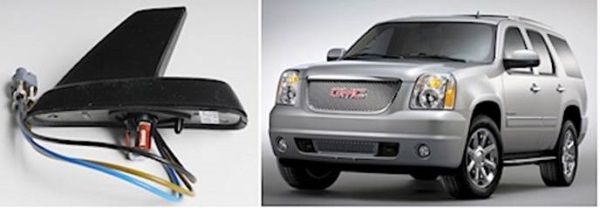
   Figure 1: The picture on the left is a generic “shark fin†antenna for the 2011 model. The picture on the right shows a shark fin antenna mounted on the 2013 GMC Yukon. The antenna module is mounted directly above the windshield. (Information: General Motors)
The module in Figure 1 includes a GPS antenna and a low noise amplifier (gain > 25 dB, noise figure < 1 dB - black line), XM satellite broadcast antenna and low noise amplifier (yellow brown cable), and a cellular antenna (blue line). Three coaxial cables terminated with special SMB connectors are secured to one housing to simplify installation. The 3 plug connector is fitted with the cable assembly inside the vehicle and has a locking function to prevent vibration and temperature cycling from separating these connectors. The entire coaxial cable can be up to 20 feet in length or more. In general, this cable is similar to RG-174. For the 2.4 GHz satellite receiver and the 1.575 GHz GPS antenna, it introduces no small losses.
In the center of the module, you can see a head bolt and a red clip that are used to secure the module to the roof. The cable shares a mounting hole with the mounting hardware. The diameter of the mounting hole is about 20 mm. Because so many vehicles are currently designed with roof-mounted modules, this hole in the roof becomes a "tight" way to get in and out of the vehicle.
There are also modules that incorporate a "short FM" antenna. They include a special matching network to allow shorter antennas to be impedance matched to RF feeds. These designs are completely specific to a particular vehicle platform. Figure 2 is an example of such a module for the 2013 Chevrolet Cruze.
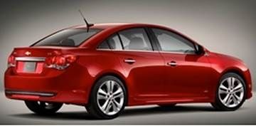
   Figure 2: The 2013 Chevrolet Cruze RS-010 with a short FM antenna module mounted above the rear windshield (close to the glass). (Information: General Motors)
Depending on the vehicle and features, the overall architecture of these signals and user interfaces may be similar to Figure 3.
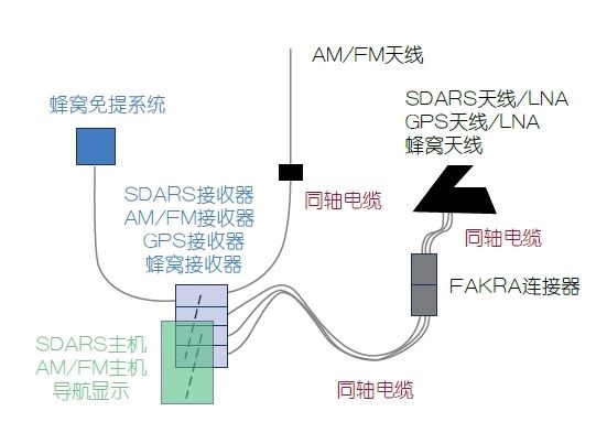
   Figure 3: Typical vehicle communication architecture in passenger cars listed around 2013.
In this topology, about 60 feet of coaxial cable is required from the roof antenna module to the in-vehicle center console, the FAKRA connector is used near the antenna, and there are more connectors at the rear of the receiver. By the way, the FAKRA connector is a special version of the SMB connector and has evolved into the standard for RF connections in cars. The connector housing has a variety of colors that have been standardized for use. For example: blue is GPS; curry yellow is satellite broadcasting. Each color has a unique pin, so there is no wrong connection.
Most of the components in these automotive communication systems are designed and manufactured by the so-called Tier 1 suppliers and supplied to OEMs. I spoke with Dr. Ayman Duzdar, Global Engineering Director, Information and Communications Division, Laird Technologies, a leading provider of Tier 1 communications solutions for the US and European markets. Dr. Duzdar agreed to share with me some of the progress we will see in a few years. Laird is already developing designs for models that are expected to be available in 2015-2019, and new technologies developed today may not appear on production cars that have been available in recent years. Dr. Duzdar explained that they are exploring ways to reduce the amount of coaxial cable and at the same time increase the connectivity to make the roof mounting unit more modular. Figure 4 is a possible construction.

   Figure 4: A possible architecture for a future connected car. WiFi, GPS and 4G receivers are moved to the roof module and then connected to the host via an Ethernet cable.
Jim Ciccarelli, head of M2M business at Laird's Information and Communications Division, told me that they also included DSRC in planning, DSRC will be between vehicles (vehicles and vehicles, or V2V), and vehicles and fixed infrastructure (V2I) Use RF communication to increase security features such as collision avoidance, routing, and providing real-time traffic information.
Since the roof is the ideal location for V2V, another antenna and RF must be added to the module. The DSRC will utilize an RF spectrum of approximately 5.9 GHz. If a coaxial cable is used to feed the signal from the roof antenna to the vehicle's mainframe, the loss can be as high as 18 dB, which is about 10 dB at the moment, which makes the new architecture even more advantageous. Comparing Figures 3 and 4, it can be seen that the electronic circuit of the center console can be simpler and can significantly reduce the number of coaxial cables and RF connectors used in the vehicle.
Laird has developed working prototype modules including 3G, WiFi (2.4GHz and 5.8GHz bands), Bluetooth and GPS receivers/transceivers. Future iterations will move to 4G/LTE, or even DSRC. Figure 5 is an example of a new module.
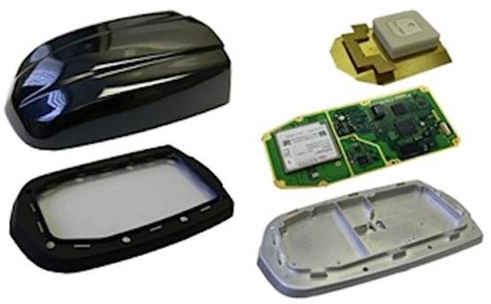
   Figure 5: Prototype of the future connection module of Laird Technologies. At the top right is the GPS patch antenna, which integrates the cellular/WiFi/Bluetooth antenna combination. The left part of the PCB (reversely the back side) is the 3G module; the rest of the PCB is for Bluetooth and WiFi. Note: The case is die-cast and can be used as a shield for electronic circuits with improved isolation Compartment. ?
Although this is an early example, Dr. Duzdar talked about the ability to download entertainment content using WiFi; the possibility of supporting WiFi for "shared" cellular connections; and the prospect of providing wireless data capabilities for rear seat passengers while driving. Imagine that in the next few years, your son/princess in the back seat of the car can use a tablet to connect to your private hotspot and use 4G networking communication.
Phone Wireless Earphones,Sports Bluetooth Earphone,Best Cheap Wireless Earbuds,Wireless Earbuds For Android
Dongguang Vowsound Electronics Co., Ltd. , https://www.vowsound.com