Abstract: Based on the design requirements and functions, this paper designs a battery management system for hybrid vehicles. The hardware system includes: power module, OZ890-based unit voltage acquisition circuit and I2C communication circuit, DSP-based RS232
Design of hardware systems such as serial communication and CAN communication; software systems include: data acquisition and processing, SOC estimation, and various communication procedures using cycle interrupts and underflow interrupts.
Keywords: battery management system; OZ890; I2C bidirectional isolation; underflow interrupt
This article refers to the address: http://
Design of battery management system based on DSP and OZ890 WANG Tao, QI Bo-jin, WU Hong-jie, LI Wei (School of Mechanical Engineering & Automation, Beihang University, Beijing 100191, China) Abstract: A battery management system for Hybrid Electrical The vehicle is designed according to its design requirements and functions. The hardware of the power system, data acquisition and communication circuit, I2C bus circuit, CAN bus circuit, RS232 circuit and so On. The software includes data acquisition and processing program based on periodic interrupt and underflow interrupt, evaluation of SOC and communication programs.
Key words: battery management system; OZ890; Dual I2C Isolator; underflow interrupt
The Battery Management System (BMS) is one of the key components of electric vehicles. A high-performance, high-reliability battery management system enables the battery to achieve optimal performance under a wide range of operating conditions. The battery management system can monitor battery status in real time, such as battery voltage, charge and discharge current, operating temperature, etc.; predict battery charge status (SOC,
State of Charge) prevents battery overcharge and over discharge, thereby improving battery performance and life and improving the reliability and safety of hybrid vehicles.
This design mainly implements functions such as data acquisition, battery state calculation, equalization control, thermal management, various communication, and fault diagnosis.
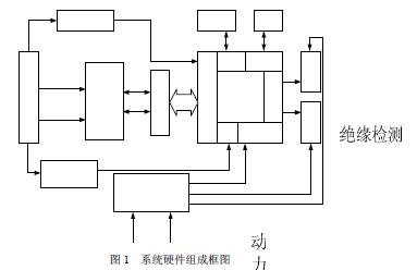
1 Battery management system hardware composition Battery management system circuit consists of power module, DSP chip TMS320LF2407A[1] (referred to as "LF2407"), data acquisition module based on multiple OZ890[2], I2C[3] communication module, SCI communication module And CAN communication module. The system hardware block diagram is shown in Figure 1.
1.1 The power supply module provides +12V power supply. The voltage required by the management system includes: +3.3V (DSP, isolated circuit), +5V (for bus driver, etc.), ±15V (current sensor), DC -DC conversion is obtained, which not only satisfies the power supply requirements of each chip but also acts as an isolation anti-interference.
1.2 The data acquisition module completes the collection of total voltage, current and temperature by the DSP. The acquisition and equalization of the battery cell voltage is performed by the OZ890 chip and sent to the DSP using the I2C bus. The circuit of this module mainly includes the front-end acquisition processing and equalization circuit.
1.3 I2C Communication Module
The OZ890 sampling module sends the acquired data to the LF2407 through the I2C bus. Since the LF2407 does not have an I2C interface itself, this design uses the PCA9564[4] to extend its I2C interface. In order to prevent electromagnetic interference from affecting the transmission of data on the I2C bus, the bus signal must be isolated. Considering that the I2C bus is bidirectional, use the ADuM1250[5]
The bidirectional isolation chip is isolated. The PCA9564 and bidirectional isolation circuit are shown in Figure 2.
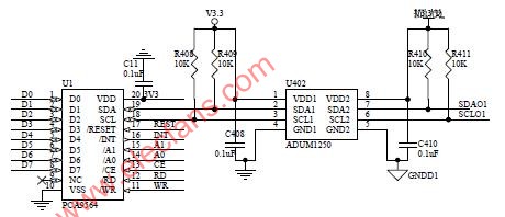
Figure 2 PCA9564 and bidirectional isolation circuit
The PCA9564 is an I2C bus extender that is connected to the GPIO port of the LF2407. It supports data transmission and reception in master-slave mode.
Set LF2407 as the master device and OZ890 slave device in the BMS. The LF2407 communicates with the OZ890 by reading and writing the contents of the four registers inside the PCA9564.
The ADuM1250 is a hot-swappable digital isolator that includes a non-latching, two-way communication channel that is compatible with the I2C interface. This eliminates the need to separate the I2C signal into a transmit signal and a receive signal for use by a separate optocoupler.
1.4 Serial Communication Module The battery management system sends the collected and processed data to the PC interface through the serial port to realize human-computer interaction. Through the serial port interface, you can observe the total voltage, cell voltage, current, SOC, fault status, charge and discharge power and other parameters of the battery, and can also realize online calibration of the management system through the serial port. Its hardware circuit is mainly based on the MAX232 chip, as shown in Figure 3a).
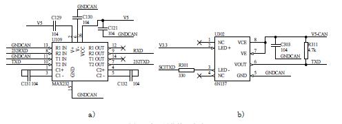
Figure 3 serial communication interface circuit
The MAX232 is a +5V power supply transceiver that interfaces to a computer's serial port to enable level shifting of RS-232 interface signals and TTL signals, enabling asynchronous communication between the BMS and the PC.
In order to prevent electromagnetic interference from affecting the transmission of data on the serial port, the bus signal must be isolated. The serial port is a one-way transmission.
Therefore, it is convenient to use 6N137 photoelectric coupling, and Figure 3b) shows the 232TXD signal optocoupler isolation circuit.
1.5 CAN communication module
CAN communication is the bridge between the battery management system (BMS) and the vehicle HCU. The BMS sends the battery status parameters to the HCU through the CAN bus. The HCU makes decisions by judging the current battery status, distributing the motor and engine. The power between them controls the charge and discharge of the battery. At the same time, the BMS can also receive the relevant commands sent by the HCU and make corresponding processing. The hardware aspect mainly provides the differential transmission capability of the bus data and the differential reception capability of the communication bus data through the PCA82C250 universal CAN transceiver. The anti-interference capability on the CAN bus is enhanced by an optocoupler isolation circuit similar to Figure 3b). Its hardware circuit is shown in Figure 4.
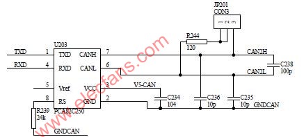
Figure 4 CAN communication interface circuit in the circuit can be connected to the 120Ω termination resistor according to the vehicle requirements, when the JP201 jumper is connected to the 1st and 2nd feet,
The resistor is not connected. When the 2 pin and the 3 pin are connected, the resistor is connected.
2 Battery Management System Software Design The Battery Management System Software [6] system consists of 6 tasks and 5 interrupts. The six tasks include: AD conversion processing tasks (including reading data in OZ890), CAN receiving tasks, CAN sending tasks, SOC computing tasks, system monitoring troubleshooting tasks, and serial port sending tasks. The five interrupts include: AD acquisition interrupt service subroutine, Timer1 underflow interrupt service subroutine, cycle interrupt subroutine, CAN bus receive interrupt service subroutine, and serial receive interrupt service subroutine.
As shown in the following interrupt vector table:
.ref _c_int0
.ref _ADC, _INT2, _INT5
.sect ".vectors"
Rset: B _c_int0;00h reset
Int1: B ADC ; 02h ADC
Int2: B _INT2 ; 04h cycle, underflow interrupt
Int3: B int3 ;06h INT3
Int4: B int4 ;08h INT4
Int5: B _INT5 ;0Ah CAN, SCI
Int6: B int6 ;0Ch INT6
According to the vehicle control strategy, the refresh cycle of the battery status data on CAN is 10ms per frame, so the clock ticks for setting the period interrupt are 10ms; the execution period of the above several tasks is set to 10ms.

Figure 5 Cycle clock beat diagram As can be seen from Figure 5, after the system initialization is completed, Time1 starts timing. When it reaches 5ms, a cycle interrupt occurs at point A, then enters the cycle interrupt subroutine, starts AD conversion, and reads through the I2C bus. Take the data in OZ890. After the AD conversion is completed, the software triggers the ADC interrupt to save the data and performs the corresponding processing to clear the period interrupt flag. When it reaches 10ms, an underflow interrupt occurs, enter the underflow interrupt service subroutine, and execute the CAN send task and SOC.
Compute tasks, system monitoring fault diagnosis tasks, and serial port sending tasks. In addition, CAN reception and serial port reception are performed using the interrupt trigger mode. Using the cycle interrupt and underflow interrupt to divide the task execution time area can not only meet the vehicle 10ms
The CAN transmission requirement of each frame of data, and each task time can also calculate the execution time of the task by the state of the counter and the flag bit, so as to better allocate the execution time period of the task.
3 Conclusion The battery management system adopts the structure of DSP+OZ890, and the corresponding anti-interference measures, featuring high performance and low cost. Due to the use of the special battery sampling chip OZ890, the sampling accuracy is improved, and the overcharge problem caused by the imbalance of the battery cell voltage is solved. At the same time, the hardware development cycle is greatly shortened, the reliability and maintainability of the system are enhanced, and good results are obtained in practical applications.
The author of this article is innovative: using the OZ890 battery sampling chip to measure battery data while using the PCA9564 extension
The I2C interface of the LF2407 implements communication between the LF2407 and the OZ890.
DC Capacitor For Electric Furnace
DC Capacitor for Electric Furnace
DC Capacitor For Electric Furnace
YANGZHOU POSITIONING TECH CO., LTD , http://www.yzpstcc.com