0 INTRODUCTION In recent years, with the rapid development of China's economy and the rapid growth of automobile ownership and the total number of drivers, the number of road traffic accidents has remained high, and road traffic conditions have become increasingly complex and deteriorating. A large number of vicious road traffic accidents have occurred in groups, which have caused great impact on people's safety and family happiness. Therefore, it is particularly important to strengthen vehicle management. Traffic safety is mainly guaranteed by two aspects. First, the vehicle has good condition and the other is the driver's standard operation. Therefore, how to monitor and manage the vehicle and regulate the driver's operation is an urgent problem to be solved.
The car tachograph, also known as the "car black box", is a digital electronic recording device that records, stores, and outputs data about the vehicle's travel speed, time, mileage, and other state information about the vehicle's travel. However, the tachograph cannot return the operation of the vehicle to the monitoring center in real time, which is post-mortem supervision, and therefore plays a limited role in preventing traffic safety accidents. The GPS/GSM-based vehicle monitoring system can obtain the position and speed of the vehicle in real time, which provides an effective way for real-time monitoring of the vehicle. However, GPS does not have access to important vehicle status information such as air pressure, water temperature, and rotational speed, so the monitoring of the vehicle is not comprehensive.
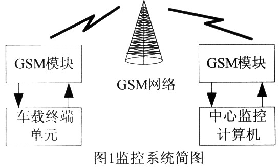
The CAN/GSM based vehicle monitoring management system was developed for vehicles with CAN bus. The vehicle monitoring equipment of the system first obtains detailed vehicle condition information from the CAN interface of the vehicle, and then communicates with the monitoring center based on the most mature and widely used GSM mobile communication system in China to realize comprehensive, dynamic and real-time vehicles. monitor. Using the CAN bus, not only can you obtain comprehensive and detailed vehicle condition information, but also make the system highly scalable. For example, the GPS module can be attached to the bus as an intelligent node of the CAN, so that the system can monitor the vehicle position. Ability.
This article refers to the address: http://
1 CAN bus technology In order to realize the communication between the huge electronic control devices in modern automobiles and reduce the increasing number of signal lines, it is necessary to transmit by means of the bus in terms of information transmission. The CAN (Controller Area Network) bus is a relatively advanced and excellent fieldbus technology that is popular today. It is a serial data communication protocol developed by Bosch in Germany in the early 1980s to solve the data exchange between many control and test instruments in modern automobiles. It is a multi-master bus, and the communication interface integrates the physical layer of the CAN protocol. And data link layer function, frame processing of communication data. By encoding the communication block, CAN ensures the dynamics of the number of nodes in the network and allows different nodes to receive the same data at the same time. The length of the digital segment is up to 8 bytes, which ensures the real-time communication. The protocol uses the CRC test to provide the corresponding error handling function, which can ensure the reliability of data communication. Since the CAN specification only includes the description of the physical layer and the data link layer, and does not define the function and implementation of the application layer, the user can use the open high-level developed by the international CAN bus user and the manufacturer association or other organizations. The agreement can also flexibly implement its own application layer in the project. In more than ten years of application, CAN has been widely used in the interconnection of industrial process monitoring equipment with its high reliability, real-time and flexibility. It has been obtained by Intel, Motorola, Philips, Siemens. Supported by more than 100 internationally renowned companies, it is recognized as one of the most promising fieldbuses. The system utilizes the above characteristics of the CAN bus to reduce the wiring harness inside the vehicle and solve the communication problem between many nodes.
2 Vehicle monitoring and management system design
2.1 System Design The vehicle intelligent monitoring system uses CAN bus technology to collect various information of the vehicle, such as the vehicle's starting time, mileage, driving time, maximum speed and duration of each maximum speed. 20 seconds of vehicle information. Then, using the existing GSM network, the information is transmitted to the monitoring center in the form of a short message to realize real-time monitoring of the vehicle.
2.2 Hardware Design The main control chip of the vehicle monitoring device adopts the 16-bit single chip MC9S12HZ developed by Freescale for automotive electronics applications. The main resources related to the MCU and the vehicle monitoring equipment are: 32~256K Flash, 2~12K RAM and 1~2K EEPROM; 2 CAN controllers compatible with CAN2.0A and B rate up to lMb/s; 2 full-duplex asynchronous serial communication interfaces; 32 × 4 segment LCD driver.
The hardware connection diagram of the vehicle monitoring device composed of MC9S12HZ is shown in Figure 2. In terms of the interface with the CAN bus, we use NXP's high-speed CAN transceiver TJAl050. In order to improve the electrical EMC and ESD performance, a common mode choke L40 and an ESD protection diode D39 are added to the circuit.
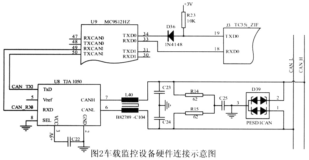
The GSM module uses a two-door TC35i that is connected to an external controller via a 40-pin ZIF (Zero Insertion Force) interface. The monitoring system only uses the SMS service of the GSM network. Therefore, the main control chip and the TC35i only need two pins of TXD and RXD, and the main controller MC9S12HZ realizes the control of the TC35i through the AT command.
The MCU and TC35i communicate through the serial port. The auto baud rate supported by the TC35i ranges from 1200 to 230400 B/s. We use a baud rate of 9600B/s. According to the TC35i manual, the serial interface requires a CMOS level, and the MC9S12HZ is a TTL level, so a level shifting circuit is required, as shown in Figure 2. The monitoring center consists of a PC and a TC35i module. The level shift between them is done by the level conversion chip MAX232.
2.3 Software design The vehicle has many operating parameters transmitted on the CAN bus, and the data volume is very large. The SMS service transmission speed of the GSM network is limited, so it is impossible to transmit all the information on the CAN bus back to the monitoring center. In fact, it is not necessary to monitor all vehicle operating parameters. It is sufficient to monitor some of the parameters that we care most about and that are most closely related to driving safety.
For different parameters, the form of monitoring is different. Some information needs to be monitored regularly, such as vehicle position information, and some information needs to be sent only when it is out of the normal range, such as speed or speed information. In addition, for different models, the parameters that need to be monitored are also different; or for the same parameter, the monitoring form and monitoring range will also change under different conditions. Therefore, the vehicle monitoring device is required to dynamically change the monitoring parameters and the monitoring form.
In order to achieve dynamic monitoring of the vehicle, a monitoring list is established in the controller of the vehicle monitoring device. Each item in the list contains the parameter group number PGN, the position of the monitoring parameter in the PGN, the form of monitoring and the monitoring time interval and the range of monitoring parameters. The items of this parameter list can be dynamically added or deleted according to the commands sent by the monitoring center, thereby realizing dynamic monitoring of the vehicle.
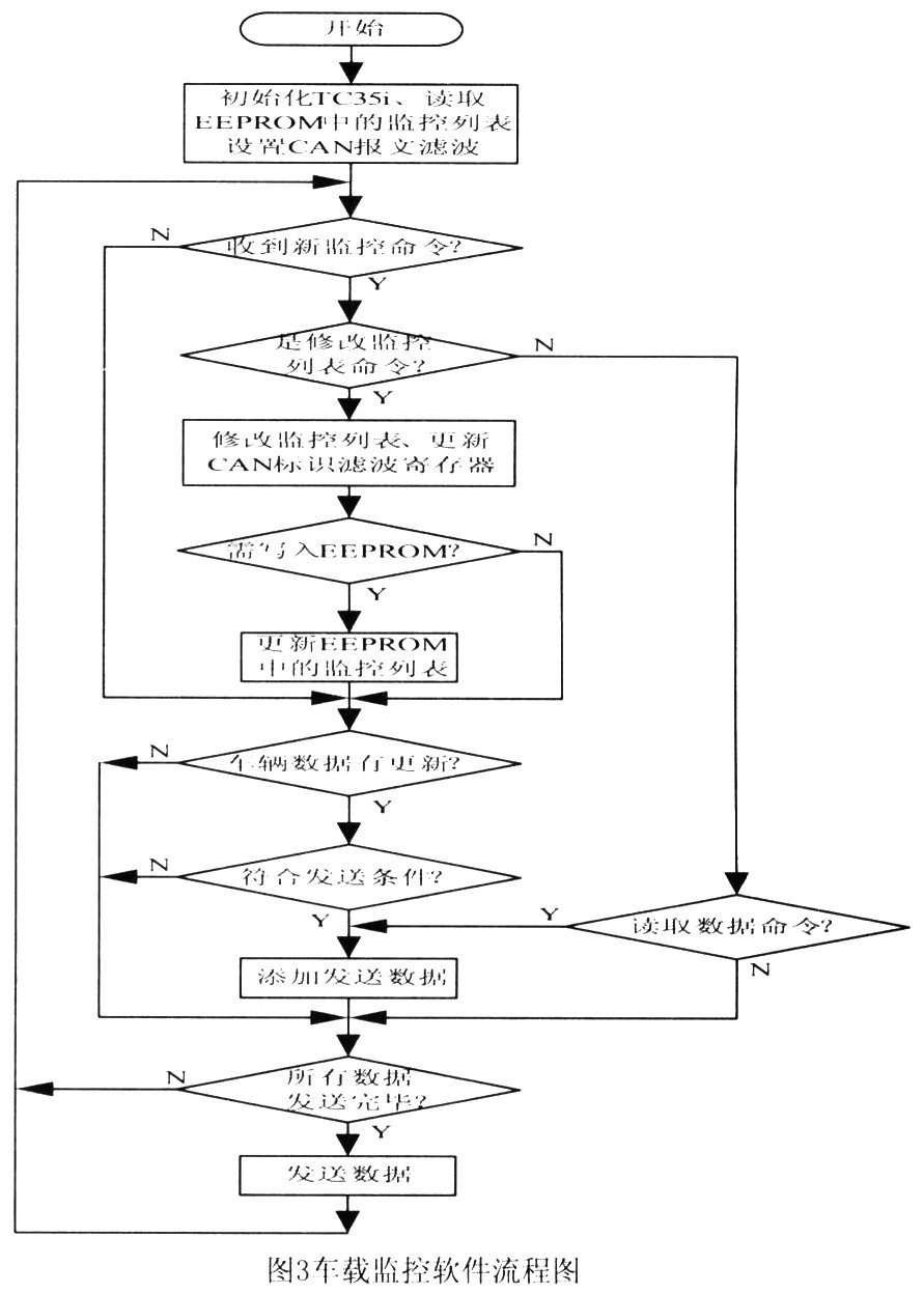
The main software flow of the vehicle monitoring equipment is shown in Figure 3. The serial communication transceiver program and the CAN bus listener are placed in the interrupt program. After receiving the corresponding command or data, the data is put into the buffer and the corresponding flag is set. The main program executes by querying these flags. The corresponding action. The main program first reads the default control list stored in the on-chip EEPROM, and sets the CAN ID message identifier filter and mask register of the MC9S12HZ according to the PGN in the monitoring list. The program can modify the list of monitoring parameters according to the command, and decide whether to change the default control list in the EEPROM according to the command. When the PGN to be monitored has new data, it is judged whether the data meets the transmission condition, such as the timing interval, whether the monitoring variable value is beyond the normal range, etc., if the transmission condition is met, the PGN and its corresponding data are added. Go to the send list.
3 Conclusion This system uses CAN bus technology to obtain various detailed information of the vehicle, and uses GSM network to communicate with the monitoring system, which not only realizes the dynamic setting of vehicle monitoring parameters, but also increases the CAN by adopting CAN bus technology. It is easy to extend the monitoring object by intelligent nodes. This greatly increases the flexibility and comprehensiveness of the monitoring system. At the same time, the GSM short message service is used for data transmission, and the connection is simple, the cost is low, and the coverage is wide.
LED Board Driver,LED Driver,LED Sensor Driver
LED Bulbs & Tubes Co., Ltd. , http://www.nsledlight.com