The car dashboard becomes the nerve center that brings together vehicle safety and manages all the information, displaying various information for the driver. In today's digital age, vehicle instrumentation systems must be able to monitor all key functions, and the system is even personalized. The development of industry demand has led to the emergence of many semiconductor solutions, from ASSP to fully custom devices. These solutions may be fixed-function solutions that do not allow for flexible product development and do not meet the designer's requirements. In contrast, the updatable solution supports multiple similar applications on a single vehicle product line without any additional cost overhead. This type of custom solution meets all needs at a low cost.
This article refers to the address: http://
This article provides an overview of an innovative CPLD architecture that completely eliminates the use of microcontrollers and their drivers, providing a low-cost, low-power combined digital dashboard solution. This analog dashboard solution (ADS) efficiently implements digital automotive networks and leverages the benefits of digital technology.
Combination dashboard solution
Traditionally, real-time output of meters such as mileage is obtained mechanically, and the display is performed using an analog drive. However, as these data inputs were digitized, stepper motors and LEDs replaced meters and gauges. An expensive microcontroller is used to process and display the digital output. The emergence of ASSP later led to higher one-time costs (NRE), which limited product updates and improvements. Product lifecycles and support for different product lines are also major factors driving the adoption of inexpensive, programmable alternatives.
A stepper motor is used on the pointer display panel to convert electrical pulses into discrete mechanical actions. When the electrical control pulses are applied to the stepper motor in a certain order, the motor shaft rotates in discrete step increments. Combined digital meters typically use stepper motors to emulate the performance and visual effects of analog panels and pointer panels, while providing very accurate positional information for digital setups. These motors need to be microstepped to achieve smooth and continuous pointer movement. In addition, the measured sample values ​​are broadcast from the vehicle sensor to the corresponding meter location, and the number of samples is limited by the bandwidth of the digital link. After a certain time interval, each measured sample value is displayed on the combination meter. On such a combination meter, it is urgent to take measures to overcome the problem that the information cannot be continuously displayed. When the sensor does not output data to the meter, ensure that the pointer is in the correct position. To solve these problems, it is necessary to increase the processing capacity, thereby increasing the cost of the digital dashboard system, and the low cost performance hinders its application in the vehicle.
CPLD-based combination instrument panel controller
It is easy to overcome the limitations of this high-cost solution with CPLD. With ADS, customers only need to update or modify the programming files in the design to achieve product replacement, so it is very flexible. In addition, new features or products can be added to the site, which not only improves the efficiency of the technology, but also meets the needs of special users and products. Using the same basic system, with a few changes, it is easy to use different devices on the new product line.
With CPLD-based ADS, product developers and manufacturers can choose from different devices as needed without worrying about outdated semiconductor components. It has a lower selling price, supports high-end features, and has a lot of room for future expansion. Its architecture uses Altera's MAX II CPLDs, which include six modules: a serial sensor data unit, a master move control and arithmetic unit, and four PWM generators. The serial sensor data unit receives input from the sensor, the main motion control and arithmetic unit performs the necessary calculations, and the PWM generator provides appropriate control signals for all phases of the stepper motor, receiving commands from the main module (Figure 1).
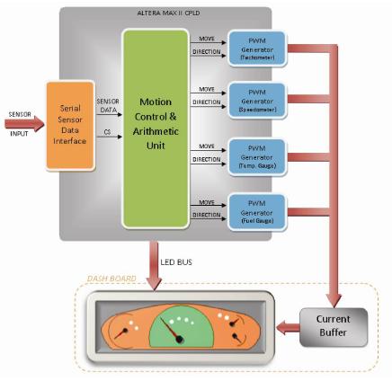
Figure 1. ADS structure diagram based on CPLD
Before describing this ADS architecture in detail, it is first necessary to understand the functions of the different modules in the narrowband vehicle data network and how the stepper motors that drive the pointer dashboard complete the microstepping control. Since all display panels of the instrument cluster do not require continuous sensor data, the system keeps the pointer position unchanged when there is no data. To achieve a smooth display, the move command sent to the pointer is the current deflection function and does not produce a rushed pointer step change.
PWM generator
Four PWM generator modules drive the pointer dashboard stepper motor to indicate data from different sensors (Figure 2).
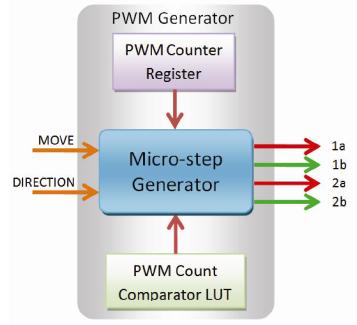
Figure 2. Basic structure of the PWM generator
The microstepping control function is used to drive the motor and produce a smooth motor rotation. In microstepping control, the magnetic field generated by the motor is not parallel to the excitation coil, but has a certain angle. In this way, the holding torque can be generated at more positions to maintain the rotor between the two pole axes of the exciting coil. When the excitation coil is energized, the resulting magnetic flux is proportional to the current flowing through it. If all of the excitation coils are energized, the current direction and the magnetic field can be obtained by the vector sum of the two winding currents. Therefore, if the current in the stepper motor winding is gradually increased, a set of equidistant positions of the excitation magnetic field can be generated to improve the step accuracy of the motor. Using this principle, the step size of the stepper motor is divided into microsteps of the actual rotation of the shaft (Fig. 3).
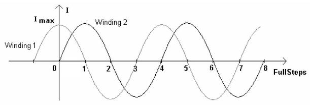
Figure 3. Two sinusoidal current waveforms during microstep control
The four PWM modules provide a constant PWM pulse with a fixed duty cycle to the stepper motor, causing the pointer to rotate at a certain speed, and the four stepping motors maintain a constant speed. They receive the movement commands from the mobile control unit as well as the directional inputs, inputting the appropriate voltage across the windings, causing each motor to rotate a microstep in the desired direction.
Mobile control and arithmetic unit
The delta generator is the main component of the motion control and arithmetic unit. The module receives a target deflection signal from each of the four stepper motors of the sensor. After receiving the target deflection signal, the two signals are sent to the respective PWM modules. One signal, the trigger pulse, changes the current duty cycle value to the next value in the PWM module. Therefore, when the span range is large, the pulse is transmitted at a higher frequency, and the PWM module quickly traverses each duty value, thereby causing the stepping motor to rotate at a higher speed. When the pointer reaches the target deflection position, the trigger pulse is stopped from being sent to the PWM module, and the PWM module outputs a pulse with a constant duty ratio, so that the rotation axis effectively maintains the position. The other signal indicates the PWM module in which direction the pointer should be rotated.
The delta generator has another important function, periodically transmitting data representing sample values. If this information is added directly to the stepper motor, the pointer will turn sharply. To avoid this rotation, the delta generator uses the corrected value, expressed as delta δ. The generator recalculates δ for this pointer value each time a new target deflection value is received. This incremental value δ is then added to the current deflection of the pointer, which is processed much faster than if the new target deflection value was received. The current deflection of the unit is continuously monitored throughout the process. When it changes, it sends a command that steps the stepper motor by one microstep in the required direction. If the target deflection value is greater than the current deflection value, it is clockwise, and if it is less than the current deflection value, it is counterclockwise.
Thus, during the interval in which the two target deflection values ​​are received, the pointer rotates at a faster rate, reaching the target value through a smaller step size, resulting in a smooth rotation. It concludes that it can cover the appropriate value of this interval and maintain a smooth rotation regardless of the input.
Sensor data input unit
The sensor data input unit uses an SPI interface to support communication with slow peripherals and can be accessed periodically. The host/slave mode communicates with the peripherals, and the data frame is initiated by the host. When the master generates a clock signal and selects the slave device, it can transmit data in one direction or two directions. The SPI slave module is implemented behind the CPLD for system input. Sensor data is imported into the arithmetic and motion control unit, which is the target deflection value for a sensor or new LED data. Sensor data is sent with the destination address to distinguish its source.
It is easy to adjust CPLD-based ADS on different platforms to improve its accuracy and achieve higher-end functions. It can provide different assembly layouts for different models, with only minor changes in the program, almost no additional cost, and the development time is exponentially decreasing. ADS can be integrated into the production process in conjunction with a reliable public vehicle digital data network, while flexible CPLDs are easy to implement.
in conclusion
Using low-cost, low-logic-density CPLDs, complex ADS can be implemented to overcome the shortcomings of traditional dashboard solutions. Because ADS has inherent programming advantages, design reuse means that more and more IP and kernel libraries can be used to quickly develop other solutions. It's easy to reconfigure and launch new products to users faster. Due to the long life cycle of the product, it is easier to recover the NRE, the manufacturer can extend the life cycle of the products that have been developed, and there is no new NRE investment.
Worm Gear Motor,Worm Drive Gearbox ,Worm Gear Reducer ,Worm Drive
Stepper Motor Co., Ltd. , http://www.nbgearmotor.com