One out of every five car failures is caused by batteries. In the next few years, this problem will become more and more serious with the popularity of telex, the launch/extinguish engine management and the hybridization of hybrid (electric/gas) technologies.
This article refers to the address: http://
In order to reduce the fault, it is necessary to accurately detect the voltage, current and temperature of the battery, pre-process the result, calculate the state of charge and the operating state, send the result to the engine control unit (ECU), and control the charging function.
Hyundai was born in the early 20th century. The first car relied on manual start-up and required a lot of power. There was a high risk. The car's “hand crank†caused many fatal accidents. In 1902, the first battery starter motor was successfully developed. By 1920, All cars have been electrically activated.
The dry battery was originally used and must be replaced when the power is exhausted. Soon after, the liquid battery (the old lead-acid battery) replaced the dry battery. The advantage of a lead-acid battery is that it can be charged while the engine is running.
In the last century, there was almost no change in lead-acid batteries, and the last major improvement was to seal them. What really changed was the need for it. Initially, the battery was only used to start the car, honk the horn and power the lights. Today, all electrical systems of a car are powered by it before ignition.
The proliferation of new electronic devices is more than just consumer electronics such as GPS and DVD players. Today, body electronics such as engine control units (ECUs), power windows and power seats are standard on many basic models. The exponentially increasing load has had a serious impact, as evidenced by the increasing number of failures caused by electrical systems. According to ADAC and RAC statistics, almost 36% of all vehicle failures are attributable to electrical failures. If this number is analyzed, it can be found that more than 50% of the faults are caused by this component of the lead-acid battery.
Assessing the health of a battery The following two key characteristics can reflect the health of a lead-acid battery:
(1) State of charge (SoC): The SoC indicates how much charge the battery can provide, expressed as a percentage of the battery's rated capacity (ie, the SoC of the new battery).
(2) Operating status (SoH): SoH indicates how much charge the battery can store.
The state of charge state of charge is like the fuel gauge of a battery. There are many ways to calculate SoC, two of which are most commonly used: open circuit voltage measurement and coulomb measurement (also known as coulomb counting).
(1) Open circuit voltage (VOC) measurement method: The open circuit voltage of the battery at no load is linear with its state of charge. There are two basic limitations to this calculation:
First, in order to calculate the SoC, the battery must be open and not connected to the load; second, this measurement is accurate only after a fairly long period of stability.
These limitations make the VOC method unsuitable for online computing SoCs. This method is usually used in an automobile repair shop where the battery is removed and a voltage meter can be used to measure the voltage between the positive and negative terminals of the battery.
(2) Coulomb assay: This method uses the coulomb count to obtain the integral of the current versus time to determine the SoC. With this method, the SoC can be calculated in real time even if the battery is under load. However, the error of the coulomb assay increases over time.
Generally, the open circuit voltage and the coulomb counting method are used to calculate the state of charge of the battery.
The operating state of the operating state reflects the general state of the battery and its ability to store charge compared to new batteries. Due to the nature of the battery itself, SoH calculations are very complex and rely on an understanding of the battery's chemical composition and environment. The SoH of a battery is affected by many factors, including charge acceptance, internal impedance, voltage, self-discharge, and temperature.
It is generally considered difficult to measure these factors in real time in an environment such as a car. During the start-up phase (engine start), the battery is under maximum load, which best reflects the SoH of the battery.
The SoC and SoH calculation methods actually used by leading automotive battery sensor developers such as Bosch and Hella are highly confidential and often protected by patents. As owners of intellectual property, they often work closely with battery manufacturers like Varta and Moll to develop these algorithms.
Figure 1 shows a discrete circuit commonly used for battery testing.
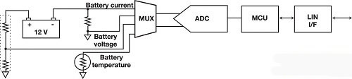
Figure 1. Discrete battery detection solution
The circuit can be divided into three parts:
(1) Battery test
The battery voltage is sensed by a resistive attenuator that taps directly from the positive side of the battery. To sense the current, a sense resistor (typically 100mΩ for 12V applications) is placed between the negative terminal of the battery and ground. In this configuration, the metal chassis of the car is typically ground and the sense resistor is mounted in the current loop of the battery. In other configurations, the negative pole of the battery is ground. For SoH calculations, the temperature of the battery must also be checked.
(2) Microcontroller
The microcontroller or MCU primarily accomplishes two tasks. The first task is to process the results of an analog-to-digital converter (ADC). This work can be as simple as performing basic filtering only, or it can be complicated, such as calculating SoC and SoH. The actual functionality depends on the processing power of the MCU and the needs of the car manufacturer. The second task is to send the processed data to the ECU via the communication interface.
(3) Communication interface
Currently, the Local Interconnect Network (LIN) interface is the most common communication interface between battery sensors and ECUs. LIN is a single-line, low-cost alternative to the well-known CAN protocol.
This is the simplest configuration for battery testing. However, most precision battery detection algorithms require simultaneous sampling of battery voltage and current, or battery voltage, current, and temperature.
In order to perform simultaneous sampling, it is necessary to add up to two analog-to-digital converters. In addition, the ADC and MCU need to regulate the Power Supply for proper operation, resulting in increased circuit complexity. This has been addressed by the LIN transceiver manufacturer by integrating the Regulated Power Supply.
The next step in automotive precision battery testing is the integration of ADCs, MCUs, and LIN transceivers, such as Analog Devices' ADuC703x family of precision analog microcontrollers.
The ADuC703x provides two or three 8 ksps, 16-bit sigma-delta ADCs, a 20.48MHz ARM7TDMI MCU, and an integrated LIN v2.0-compatible transceiver.
The ADuC703x series integrates a low dropout regulator on-chip that can be powered directly from a lead-acid battery.
To meet the needs of automotive battery testing, the front end includes the following devices: a voltage attenuator for monitoring battery voltage; and a programmable gain amplifier that, when used with a 100mΩ resistor, supports measuring full-scale currents up to 1A to 1500A; Controller, supports coulomb counting without software monitoring; and an on-chip temperature sensor.
Figure 2 shows the solution using this integrated device.
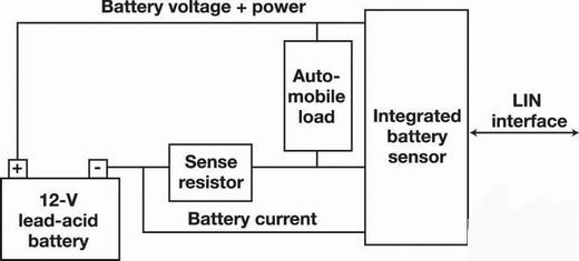
Figure 2. Example of a solution with integrated devices
A few years ago, only high-end cars were equipped with battery sensors. Today, there are more and more mid- to low-end cars with small electronic devices installed, which were only seen in high-end models a decade ago. The number of faults caused by lead-acid batteries is therefore increasing. In less than a few years, each car will be equipped with a battery sensor, reducing the risk of failure of an increasing number of electronic devices.
Variable Ac Power Supply model SP300VAC5000W is switching mode single-channel output it adopts high speed DSP+CPLD control, high frequency PWM power technology and active PFC design to realize AC/DC stable output. This Ac Power Source is featured with high power density, high reliability and high precision, meanwhile it possesses operation interface of touch screen and keys manually. It is able to analog output normal or abnormal input for electrical device to meet test requirements.
Some features of the ac source as below:
- 5.6"large touch color screen
- AC+DC mixed or independent output mode
- Capable of setting output slope/phase angle
- Built-in IEC standard test function
- Built-in multiple protections
- Built-in power meter
- Support impedance function
- Support for LIST/PULSE/STEP mode & Transient mode
- Standard RS232/RS485/USB/LAN, Optional GPIB/multiphase card.
- Support master and slave parallel mode to realize power extension
- Support harmonics/inter-harmonics simulation and measuring function
- Support for USB data import/export and scree nap from front panel
- PWM technologies, with up to 86% efficiency
- CE, CSA, UL, ROHS Certified
5000W Ac Power Supply,3 Phase Ac Power Supply,Industrial Switching Power Supply,Ac Adjustable Power Supply
APM Technologies (Dongguan) Co., Ltd , https://www.apmpowersupply.com