How to make a tube amplifier
One. Tube selection 1. Power tube The selection of power tube is directly related to the output power of the amplifier. Most high-definition audio amplifiers designed for music enjoyment in the tube age are mostly low-power amplifiers. In the early 1960s, the author worked in Shanghai. I like to go to the Tibet Middle Road Music Bookstore on holidays and linger in front of the record counter. I was deeply attracted by the sound of nature from the 10W output push-pull amplifier. At that time, the paper cone paper folding ring speaker was very sensitive, and the speaker did not have the loss of crossover network. 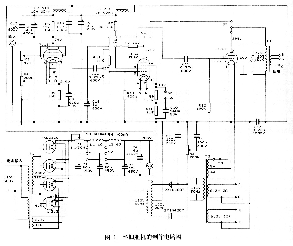 This machine is for family to enjoy leisure music, without much output power, it is enough to use one classic direct-heating transistor 300B for each channel. There are a lot of articles about 300B in many audio magazines, so I won't go into details here. However, it should be pointed out that it is very important to control the power dissipated by the screen when using power tubes. Exceeding the maximum screen consumption will cause the tube to burn quickly, which is absolutely not allowed, and in reality this situation rarely occurs. On the contrary, most audiophiles cherish the tube too much, and the screen consumption is adjusted very low, only half of the maximum screen consumption or even 1/3, which is also inappropriate. The correct approach is that the actual screen consumption is controlled at 80% to 90% of the maximum screen consumption, which can achieve a balance between the life of the tube and the output power. The voltage between the cathode and the cathode (filament) of the 300B screen of this machine is to be 300V, the current of the screen is 73mA, the power dissipation is 22w, and the effective output power of 6W is guaranteed. There is another interesting question about playing 300B: Does the filament power supply use alternating current or direct current? Many players discuss from a technical perspective. The author's opinion is that this is not a comparison of technical advantages and disadvantages but a personal preference. I use AC power to light the 300B filament, which is the nostalgic atmosphere! 2. Voltage amplifier tube The input stage voltage amplifier selects Amperex brand 7119 made in the Netherlands, which is a selection of high-quality dual triode electron tubes. The tube is a nine-legged peanut tube with a diameter of 22.2mm and a tube height of 60ram. In the age of computer tubes, 7119 is mostly used in limiting circuits. Filament voltage Uf = 6.3V / 12.6V, current If = 0.64A / 0.32A, internal resistance 1.6k Ω, amplification factor μ = 24, screen current Ia = 36mA, single screen maximum screen consumption Pa. 1 = 4.5W, the maximum screen consumption of dual screen Pa.2 = 8w. Low internal resistance, large screen flow, strict quality control, and good consistency of the parameters of the two transistors are the reasons for choosing this tube. Similar tubes are 5 6 8 7 and E182CC.
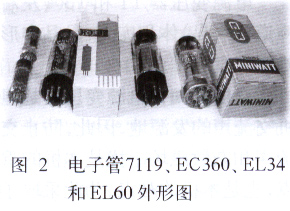
The push tube is made of EL60, and its characteristics are exactly the same as the EL 34, but the pins are different. The EL 34 is a common large eight pin with a latch, and the EL60 is a nine-pin self-locking pin, which is very special. EL60 has a dual role in this machine, which is not only the 300B push tube but also the final power tube through the switching circuit. When used as a power tube, it is in a single-ended Class A amplification state, the power supply voltage of the EL60 screen is 250V, the screen current is 100mA, the curtain grid current is 14mA, the grid negative voltage is 13V, the optimal load impedance is 2.8kΩ, and the output power 10W. The above set of parameters is very different from the working parameters of EL60 when it is used for class A and B push-pull amplification, so you need to pay more attention when designing the circuit. It should be pointed out that EL60 has a very high power sensitivity in the Class A state and is easy to push. Use level 1119 as voltage amplifier to push it to full power output. 3. Rectifier tube As a nostalgic tube amplifier, high-voltage DC power supply using tube rectifier is the only option. The load current is initially estimated to be 220mA, and the output current of the rectifier should be considered as 250mA. Direct heating rectifiers such as 80, 5U4, etc. are excluded first. The thermal inertia of this kind of tube filament is small, and the filter capacitor is charged to the peak almost immediately after starting, and the soft start effect cannot be achieved. I have also considered the EZ80, EZ8 l, 528P and other side-heating pipes, but also think that its shape is not compatible with 300B and EL60. After repeated trade-offs, the non-dedicated rectifier tube EC360 was selected, with a tube diameter of 28mm and a tube height of 95mm, and the shape is similar to the EL60. It can be seen from the serial number that the tube is a single triode with a filament voltage of 6.3V. The oval cathode has a large surface area, the grid wire is close to the cathode, and the outside is surrounded by the screen. The distance between the screen and the cathode is very close, only about 2mm. This distance is very important for the rectifier tube. If the distance is too large, the internal resistance of the tube is high, and the rectification efficiency is low. On the contrary, the tube has a low reverse peak pressure and is easily broken. The EC360 screen grid distance is 2mm, and it is not a problem to withstand the 1500V reverse peak voltage. In actual use, the EC360 grid is left unused (do not connect it to the screen through a current limiting resistor), so that the grid is at a free potential, so that the tube is safer. The high-voltage power supply of this machine uses four EC360s for full-wave rectification, and two for each arm, which not only reduces the internal resistance of the power supply but also ensures that there is enough rectified current output. Practice has proved that when the voltage of the secondary side high-voltage winding of the transformer is 300V, the filter input capacitor is 80 "F, and the load current is 212mA, the EC360 rectified output voltage reaches 334V, and there is no flashover in the tube, achieving safe and efficient operation.
two. Local circuit
This machine is a traditional nostalgic tube amplifier, using a classical circuit: the high-voltage power supply part is equipped with an LC filter network for full-wave rectification of the tube, and the amplification part is a common cathode amplifier circuit. Figure 1 is the circuit diagram of this machine. The switch in the picture is in the position where EL60 is the push tube and 300B is the power tube. 1. Power supply The left and right channels share a high-voltage power transformer Tl and a grid negative voltage power transformer T2, and the filament power transformer T3 has one left and right channels, and the circuit diagram shows only one channel. The whole machine is powered by 110V: the primary winding of the electron tube 7119, EL60 and 300B filament transformer T3 is 110V. Originally, the 220V power supply can be used by connecting the two transformers of the left and right channels in series, but this will reduce the safety of the whole machine and increase the inconsistency of the left and right channels, so in the end it was decided to use 110V for power supply. Of course, audiophiles are troublesome in imitation, and they can directly use the 220V power supply in series. The gate negative pressure is obtained by transistor rectification to ensure that the 300B is protected as soon as it is turned on. The output voltage of B + power supply is adjustable. The filter capacitors Cl and C2 are respectively connected to the switches Sl and S2, and the mutual conversion between the capacitor input filter circuit and the inductance input filter circuit can be realized by switching; in addition, the DC output circuit is connected with a variable resistor R1 with large power consumption. The combination of the above two methods can adjust the DC high-voltage output in a large range to meet the needs of different power tubes. A voltmeter V0 is connected across the output of the filter circuit: in addition to monitoring whether the rectifier and filter circuit are working properly, the voltmeter V0 can also determine the DC power consumption of the whole machine. The internal resistance of the voltmeter V0 is 350kΩ, which also serves as a bleeder resistance. 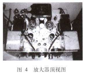
2. In the power tube switching circuit of the amplification part, when the power tube is switched from 300B to EL60, the EL60 changes from the three-pole state to the standard state. The curtain gate is connected to the B + power supply through the resistor R7, and the gate is serially connected to the anti-vibration resistor R13 of lk Ω The resistor R9 is short-circuited. At the same time, lower the B + voltage to 250V. Please note that the push pin identification in the circuit diagram is for EL34, because I cannot buy the nine-pin self-locking socket for EL60, so I have to use the eight-pin socket instead. The pin markings of EL60 are: 1, 9 filaments, 8 cathodes, 7 control grids, 6 curtain shed poles, 2 suppression grids, and 3 screen poles. The input potentiometer in the input impedance conversion circuit doubles as the volume control, and is composed of R3 and R4. There is an isolation capacitor at the output of the CD player. Normally, R4 can be shorted, and R3 can be used to adjust the volume. The R3 resistance value is 47k Ω, which is a heavy load for CD players, but for the electron tube 7119, the gate resistance is low, it is not easy to infect noise, the signal noise is relatively high, but the gain is low, otherwise. R4. The sliding arm moves down, the gain increases, and the signal-to-noise ratio decreases. The output transformer T4 of the power tube screen current monitoring part is connected across the voltmeter Vl at both ends of the primary winding. The resistance of the primary winding is known to be 203 n. The screen current can be obtained by reading the voltmeter. The internal resistance of the meter is 50kΩ, and parallel connection with the output transformer will not affect the output impedance. The negative feedback resistor R9 does not have a bypass capacitor, which makes the EL60 use current negative feedback when used as a push tube. In addition, there is no negative feedback circuit. The open-loop gain of this machine is not high. By accurately selecting the working point of the tube and monitored by the voltmeter Vl, the distortion is maintained at a low level. The internal resistance of 300B is very low, coupled with the acoustic damping of the speaker and the mechanical damping of the speaker, there is no need to use negative feedback to increase the output damping coefficient of the amplifier. It should be known that the output of several watts in the 300B area is very precious. The parallel decoupling circuit uses parallel decoupling, and its performance is better than the commonly used series mode, and the amplifiers work more stable at all levels.
three. Selection of components
Make nostalgic amplifiers. The key lies in the selection of components. Under the premise of quality assurance and reasonable price, antique parts are used as much as possible, which is difficult to find. It is also a pleasure to search for parts patiently. 1. Tube purchase The author is an amateur radio enthusiast and likes to visit the electronic flea market. The Dutch Amperex 7119 tube was bought from a stall. In the large family of electronic tubes, 7119 is a late-stage product, and there are few social reserves, which are rare to meet. EL60 is a Miniwatt brand produced by Philips in the Netherlands. It is a new tube with a box. I bought 5 of them. The actual flow rate of the 5 tubes is no more than 5%. As for EC360, audio enthusiasts can see mail order news from relevant magazines, but the author ’s EC360 was bought from an electronic stall a few years ago, and it is also a new tube with a packaging box, former East German R. F. T brand. Figure 2 shows the electron tubes 7119, EC360, EL34 and EL60 from left to right. The well-known 300B has a wide range of brands on the market, and the difference between high and low prices is two orders of magnitude. Is it worth it? Different opinions, I choose the domestic Shuguang 300B-98 type. The manufacturing of electronic tubes is mostly a manual process, and the parameters of the finished tubes are very discrete. It is not easy to find matching tubes with the same performance. The whole machine debugging in the future also confirmed this. In order to pursue the same performance of the left and right channel 300B-98 tubes, the author has returned to the store five times to exchange the tubes, and the difference between the screen flow of the two tubes is less than 5%. This is still a static parameter. As for dynamic parameters, it cannot be measured under amateur conditions.
2. Other components The grid negative voltage transformer T2 is a DB-201-367 transformer of Shanghai Radio No. 27 Factory, which was originally a two- or three-lamp reciprocating AC radio power transformer. Primary side winding 220V, secondary side high voltage winding 210V, used in this machine primary side voltage 110V, secondary side through transistor rectification to obtain a 148V voltage supply 300B gate negative voltage. The choke coil L3 (both channels shared) in the decoupling circuit of the electronic tube 7l 19 is also a product of Shangwu 27th Factory, which is a ZL-1010-113 type choke coil. The choke coil L4 has one left and right channel, the right channel is replaced by Shanghai brand 163-7 type six-lamp electronic tube AC ​​radio output transformer, and there is no CB-2 75 output transformer of the 27th factory above the left channel. The high voltage power transformer Tl is American Federal Tel. The disassembled product produced by & Radio Company has a quality of 7.5kg. The filament power transformer T3 of the electron tube 7119, EL60, and 300B is also a disassembled product made in the United States and is produced by Saratog Industries, with one for each channel and a single mass of 4.3 kg. The filter choke coils Ll and L2 are made by the American Bendix Radio Division 0f Bendix Avia-TIon company, with a single weight of 5.5 kg. The output transformer T4 comes from the hands of folk audio enthusiasts. The cross-sectional area of ​​the iron core is 3.4cm (tongue width) × 6cm (stack thickness), and each mass is 3.9kg. The primary side inductance was measured with VC6240 digital LC meter l 8.8H / 18.4H. , DC resistance both are 203. Attentive readers will find that the total mass of the seven inductance components mentioned above-T1, 2 × T3, L1, L2 and 2 × T4-reaches 35kg. The filter capacitors C1 and C2 are sprague clamp fixed electrolytic capacitors. Cl was produced in December 1951 and c2 was produced in February 1952. It has been more than half a century since! The electrolytic capacitors come with original sockets. C4 is Sibi oil-immersed high-pressure paper canned capacitors. The decoupling capacitors C5 (one for each of the left and right channels) and C6 are triple-mounted Sibi negative electrode aluminum shell old-style socket electrolytic capacitors with original sockets. The cathode bypass capacitor C9 is Siemens electrolysis, and C10 is Sibi old paper shell electrolysis. Inter-stage coupling capacitor C11 is Sibi's Vitamin Q capacitor, and C12 is West Cap capacitor. The voltmeter V0 is a product of Weston Company of the United States, with a measuring range of O ~ 350V. t000Ω / V, dial diameter 63mm. The voltmeter V1 is a product of American A & M Instruments, with a range of 0-50V, 1000Ω / V, and a dial diameter of 63ram. Volume control potentiometer R3 is ALPS special potentiometer for large audio, R4 is Noble old-style steel potentiometer.
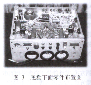
four. Installation process All parts must be tested before assembly to confirm that they can be used on the machine. This is very important and can save a lot of time for future debugging. For the power transformers Tl, T2, T3, first measure the DC resistance of each winding, confirm that there is no short circuit, and then carry out the no-load test. Connect the power supply and measure the voltage of each group. Note that the no-load voltage should be about 5% to 10% higher than the rated value. The no-load test needs to last for 2 hours to observe whether the temperature rise of the transformer is normal. For the output transformer T4, choke coils L1, L2, L3, and L4, in addition to measuring the inductance, the DC resistance of the coil must be measured and recorded, so that the current value through the element can be calculated in the future. All capacitors must be measured for capacitance value, and cannot be a fluke. Older electrolytic capacitors with more serious leakage cannot be used! Variable resistor Rl is a sliding wire resistance, and the power should not be less than 50W. DIY audiophiles know that the chassis is the biggest headache in the production of amplifiers. The chassis and panel of this machine are derived from a US-made radio frequency instrument. The size of the chassis is 430mm × 330mm × 75mm, aluminum alloy, thickness 2mm. The parts that must be installed on the chassis are: 10 electron tubes, 4 power transformers, 2 output transformers, 4 filter and decoupling electrolytic capacitors, the adjustment knob of the variable resistor Rl and the rotation of the grid negative piezoelectric potentiometer R2 axis. To compare again and again, determine a reasonable layout plan, draw a drawing, and then process the chassis according to the drawing. The processing chassis is all fitter work. Under the conditions of the family, there is a lack of sophisticated tools and no dedicated workshop. The author has a small bench on a small balcony, a pair of abandoned speakers and serves as a workbench. Drill, chisel, Saw, grind, file three times and five times, just bite this bone down! The chassis area is limited, can not put all the large components, filter choke Ll, L2, high-pressure oil-immersed paper canned capacitor C4 had to use an external arrangement , Connected to the host through a connector. Three voltmeters are installed on the panel for easy monitoring. The choke coils L3, L4 (one for each of the left and right channels) and most of the RC components are installed under the chassis. The peripheral components of the electron tube should be welded as close as possible to the tube base, and the component should be fixed with an insulating bracket. The component should not be close to the bottom plate, which is the "shack type" structure as the saying goes. For non-factory machines, there is no need to deliberately arrange the components perpendicular to each other and bundle the wires together. The power transformers Tl and T3 (one for each of the left and right channels) are huge and dominate the three sides of the chassis in the shape of a letter. As we all know, the power transformer is the source of the hum of the tube amplifier. Therefore, preventing the interference of hum and stray magnetic fields is the focus of this machine and the difficulty of this machine. To this end, the following measures have been taken: The filament circuit is an important source of hum. The center tap of the 300B filament winding must be grounded, and the grounding point should be close to the 300B tube base to balance AC hum. The filament power cords of 7119 and EL60 must be twisted with two wires, close to the bottom plate and single-wire grounded, but the filament of the rectifier EC360 must not be grounded to avoid the insulation between the cathode filaments being broken! Once the input circuit is infected with noise, the In the future, all levels of amplification will cause serious consequences. The volume of the volume potentiometer should be well grounded. The wire should be shielded and the shield should be grounded at one end. The choice of grounding point has a great influence on the hum. The grounding points of the same tube should be connected together to the chassis. Use a screw nut and a spring washer to press the grounding pad to the aluminum plate to minimize the grounding resistance. The grounding points at all levels should be arranged in order of signal flow. All components, sockets and brackets must be thoroughly derusted and soldered in advance before being put on the machine. A soldering iron is not enough for a soldering iron. In addition to 25W, a 75W soldering iron is required. Use high-quality wire for the internal cable, and have a certain rigidity to avoid wire shaking. The author likes to use the inner conductor of the horn cable, but it is necessary to pay attention to whether the insulation layer is sufficient, and if necessary, use an insulating sleeve. The arrangement of parts under the chassis is shown in Figure 3. The top view of the amplifier after the completion of the assembly operation is shown in Figure 4, and you can see at a glance that it is a nostalgic amplifier.
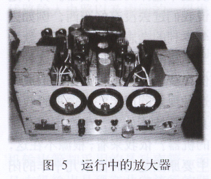
Fives. Debugging of the whole machine After welding, the circuit must be checked again and again to confirm that it is correct, and then debugged according to the following steps. Beforehand, you need to prepare an autotransformer. The power supply is connected through the autotransformer, and the voltage is slowly raised to l 10V. During the boosting process, pay close attention to whether there is any abnormality in the machine. (1) Don't plug in the electron tube, connect the power supply, the voltage is adjusted to 1 10V, measure the voltage of each group in detail: AC high voltage, the filament voltage of each electron tube. Note that the gate negative pressure circuit is working at this time, adjust R2 to the maximum negative pressure, measure the negative pressure, there should be 148V, special attention should be paid to the polarity of the negative pressure of the shed! Rotate the R2 shaft, the negative pressure should change smoothly, and there should be no jump . (2) Just plug in 7119, EL60 and 300B, power on to 110V, and measure the filament voltage of each tube with the filament load connected. (3) Unplug 7119, EL60} I] 300B, plug in EC360, slowly boost with an autotransformer and monitor the voltmeter V0 so that it does not exceed the full scale of 350V, pay close attention to whether there is a flashover in the machine. (4) Put R at the maximum negative pressure position, plug in all the electron tubes, connect the load, and slowly energize the booster. When the V0 reading of the voltmeter reaches 300V, suspend raising the power supply voltage. Adjust R2, slowly reduce (the absolute value becomes smaller) the negative voltage of the grid to a certain value, the pointer of the voltmeter V1 begins to deflect, indicating that there is a screen flow at 300B. After the screen current appears, the V0 pointer of the voltmeter has dropped, and the power supply voltage should be raised to l again. | 0V, at the same time adjust the negative gate voltage so that V1 does not exceed 15V, the corresponding screen current is 74mA. At this point, the whole machine is in working state, connected to the audio source, and it should be able to play under normal conditions. Figure 5 is a nostalgic tube amplifier in the running state, please pay attention to the deflection of the three DC voltmeter pointers on the panel. For Class A amplifiers, the pointer of the voltmeter V1 should not swing under normal operation. If the pointer swings to the right, it means that the negative pressure of the power grid is too low (the absolute value is too large). R2 should be carefully adjusted to increase the static screen current (be careful not to exceed the maximum screen consumption of the tube). If the pointer swings to the left, the reverse To adjust. (5) When it is necessary to switch the power amplifier tube from 300B to EL60, first turn off the power, toggle each switch in the power-off state, the filter circuit is changed to the inductance input type (in the circuit diagram, the switches Sl and s2 are turned down ), The variable resistor Rl is adjusted to the maximum value, and then turned on. Practice has proved that in order to make EL60 B + power supply 250V, just connect L1 to input inductance and R1 to 80Ω. At this time, voltmeter V0 reading is 250V, voltmeter vl reading is 20V, the corresponding EL60 screen current is 99mA. (6) When the EL6011 is used as a power tube, the working point is controlled by the resistor R10. As long as the resistance of R10 is changed and the B + power supply voltage is adjusted accordingly, a variety of power tube models can be replaced. For example, 16F6, 6V6, 6L6, KT66, KT88 and 6GB8, etc., enjoy the fun of playing bile. After the commissioning is completed, the voltage of the key points of the whole machine is re-measured and recorded. The voltage value marked in the circuit diagram is the value when the power tube is 300B.
six. Evaluation of sound quality Any newly installed audio amplifier needs a trial operation process to reach a stable state, which is commonly known as a boiler for audiophiles. This machine has been used for more than half a year, and it is time to evaluate the sound quality. 1. System description The system configuration revolves around the theme of nostalgia: the sound source is the Rorgers SC-8i CD player, and the playback system uses the Feile brand YD5-2502 type produced by the Shanghai Radio 11 Factory for the high-definition system in the 1970s 10-inch dual paper cone full range electric speakers. The speaker is a bass-inverted floor box. The size of the box is designed by yourself and entrusted to others to process. The installation of the speaker, the design calculation of the sound absorbing material, and the selection and pasting are all hands-on. Feile brand YD5-2502 loudspeaker has a resonance frequency of 55 Hz and an effective playback range of 50 Hz to 12 kHz. This range has covered most of the music spectrum. In order to further expand the high frequency band, the author connected a pair of inverted Dynaudio MSP-110MKâ…¡ bookshelf boxes in parallel. Don't worry about the parallel connection of two pairs of speakers will affect the impedance matching with 300B, because 300B is a low internal resistance transistor, the load impedance is not strict, the load impedance is larger, the output power will be smaller, and the distortion is also less; If it is smaller, the output power will increase but the distortion will be larger. Because the sensitivity of the two pairs of speakers is far from each other, the sound mainly comes out of the white floor box. The main function of the bookshelf box is to increase the high-frequency color. The listening environment is an ordinary 16m2 home living room with an asymmetrical pattern and no acoustic treatment.
4K HD LED Display Stunning life-like images with 4K UHD resolution and Intelligent Picture Quality to transform content from any source to UHD
High-quality bright LED dot matrix module with painted ink color evently is not easy to be damaged and ensures the best viewing angle
Constant voltage chip driving reduces the power consumption and prompts the stability. Simple modular design is low cost and easy to maintain
Neat appearance, light weight, small size and safe 5V low voltage power supply system all make the module more attractive
Advanced video processing. With our extensive experience in image and video processing, the LED displays provide you with the ultimate image quality assurance, color uniformity and cost of ownership.
Featuring high resolution and high brightness, it can keep high contrast level even in strong sunlight.
The replace for modules costs few, without changing the original structure.
16:9 Golden division ratio. It can be point to point spliced to the led screen of standard 720P ,1080P ,2160P , 3840P ,etc.
Anti-slid handle design. Easy for transportation ,loading and uploading.
High strength Aluminum alloy material. The integral die-casting aluminum molding workmanship has provided with excellent flatness of the cabinet.
Ultra wide viewing angle , different experience. Both 140 from horizontal and vertical for the viewing angle. Seeing from different directions,it would be still the natural and clear image in an led screen.


4K Hd Led Display,4K Hd Led Screen,4K Uhd Led Display,4K Tv Hd Screen
Shenzhen Bako Vision Technology Co., Ltd. , http://www.rentalleddisplays.com