Electrification, intelligence, and interconnection are becoming new trends in vehicle development, start-stop systems for fuel economy, advanced driver assistance systems (ADAS) to increase active safety, and driving information systems as the basis for a new generation of intelligent transportation. More and more electronic systems are being adopted by automotive designers. The integration of multiple systems has brought challenges to automotive power supply design while improving the driving experience of automobiles. Automotive power supplies must provide higher energy efficiency and lower energy consumption to meet the development of the automotive industry and comply with various environmental regulations and safety standards.
Linear Scheme Comparison Switching Scheme (SMPS) and Design Considerations
Inevitably, heat is generated during the power conversion process, and the heat dissipation of the regulator loses a part of the power, so that the output power cannot be equal to the input power. Traditional linear regulators dissipate most of the energy in this process and are no longer sufficient for current high power demand applications. We assume a linear regulator requires 2.5 W of rated power, and a 5 V output voltage and 0.5 A output current, then 6 W of input power is required, and the energy efficiency (ie, the ratio of output power divided by the input power) is only 41. %, the loss is as high as 59%! In the same situation, the switching power supply requires only 2.8 W of input power, and the energy efficiency is as high as 90%.
Therefore, design engineers can use switching power supplies to improve system energy efficiency, but switching solutions also have drawbacks. Due to their complex feedback loops, external components are more linear than linear solutions and require more PCB area, coupled with the nature of the switch, resulting in noise reduction performance. Poor, in the design process, it is necessary to consider the feedback loop design, the number of external components, PCB area, transient current and electromagnetic interference to alleviate its drawbacks.
Feedback loop design
Select a suitable negative input resistor for the post-regulator matching the output impedance to avoid oscillation and achieve the purpose of regulated output;
Effective use of simulation tools to understand frequency compensation in the frequency domain; frequency compensation can be achieved by selecting a unipolar response control scheme.
2. Number of external components
The integrated power switch reduces wiring size, consumes less power than off-board power switches, and is easier to design.
3. Circuit board area
By reducing the size of the inductor and capacitor, the board area is reduced, and the switching frequency is increased, which improves the energy efficiency and reduces the electromagnetic radiation and electromagnetic interference of the PCB. However, care should be taken to minimize conduction and switching losses and reduce noise.
4. Transient current
Parallel connection of the linear regulator and the switching power supply reduces the transient current, called a hybrid switching power supply; and pulse frequency modulation with constant on and off conditions depending on line load conditions.
5. Electromagnetic interference
Reduce loop area and optimize PCB layout to reduce interference between circuits;
Avoid sensitive frequency bands generated by the regulator and system environment;
Spread spectrum modulation techniques, spectral content and decoupling schemes are used to reduce emissions peaks.
In automotive applications, it is also necessary to consider the increasing complexity of the power management module, the ability to handle higher current conditions, low dump, dual battery transfer, and even minimum operating current, etc., to select the appropriate energy efficient power supply for the system. Program.
Hybrid linear/switching power solution for low voltage start-up
In the context of the increasingly stringent fuel economy standards and regulated CO2 emission agreements in various countries, the market demand for start-stop systems is increasing. The so-called start-stop system, that is, automatically shuts off when the vehicle is temporarily parked during driving, and the system automatically restarts the internal combustion engine when it needs to continue, thereby reducing the idle time of the engine to reduce fuel consumption and carbon dioxide emissions.
The internal combustion engine cannot be started by itself, and an external force is required to initiate the combustion cycle. This is where the starter motor is used. When the ignition key is inserted and the switch is turned "on", the motor starts. However, the amount of current required to start the motor to crank the engine is very large, resulting in a significant drop in the car battery voltage during the start-up phase. To avoid voltage drops during the startup phase, a start-stop pre-boost is added between the buck regulator and the battery-powered LDO. It is based on the ignition switch on and off to meet the low-voltage start-up of the start-stop system. Pre-boosters typically use high-power centralized multiphase boost and distributed low-power single-phase boost to avoid anomalies caused by voltage dips and comply with the ISO 16750 standard for 12 V systems. For example, ON Semiconductor's non-synchronous boost controller NCV8876 operates from an input voltage of 2 V to 45 V and can operate under cold start and 45 V load dump. The working principle is: NCV8876 goes into sleep when the battery voltage is normal. Mode; when the battery voltage drops to the set voltage, the NCV8876 automatically wakes up and starts boosting. The NCV8876 also integrates a variety of protection features such as cycle-by-cycle current limit protection, discontinuous mode overcurrent protection, and thermal shutdown. Other features include peak current detection, minimum COMP voltage clamping for improved response speed during switching, and an operating temperature range of -40°C to 150°C, making them ideal for automotive start-stop systems.
ADAS increases output power with a hybrid linear/switching power scheme
As the importance of active safety systems for vehicles increases, ADAS gradually expands from high-end applications to mid-range vehicles. It provides a safer and more convenient driving experience, such as adaptive cruise control, blind spot monitoring, by assisting the driver in controlling the complex process of the vehicle. Lane departure warning, night vision, lane keeping assistance, and collision warning systems with automatic steering and braking. The next generation of ADAS will further automate the driving experience, such as: using the smart phone app to assist with automatic parking; equipped with V2X communication system to realize instant information exchange between vehicles and vehicles or vehicles and the external environment, thereby greatly alleviating traffic congestion and reducing traffic accidents. Identify potential hazards through a media radar sensor platform, react sensitively and take action on its own, providing multiple safety features while reducing costs.
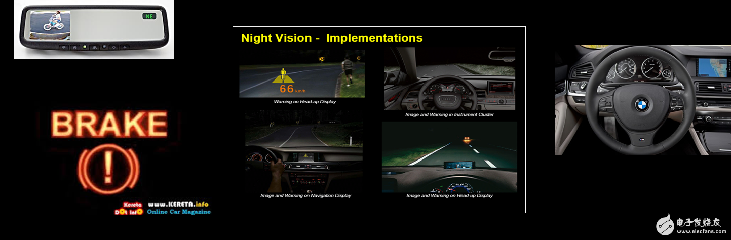
Figure 1: Advanced Driver Assistance System (ADAS)
This requires a System Basis Chip (SBC) to be successfully connected to various parts of the vehicle such as cameras, GPS, radar and rotary encoders via communication technologies such as Ethernet. Due to the high integration complexity of ADAS, system designers need to select high-precision and customizable power and power modules for them, providing dedicated functions such as watchdog function, power monitoring redundancy, and voltage monitoring for the power supply unit. Guaranteed to comply with the ISO26262 standard for Automotive Safety Integrity (ASLI) B, for complete vehicle functional safety and a safer driving experience.
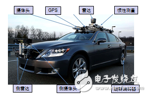
Figure 2: Ethernet SBC technology to achieve ADAS integration requirements
Driving information system uses switching power supply scheme to reduce transient current
The driving information system includes information systems, communication systems, and entertainment systems inside and outside the vehicle, and is a major part of the development of automobiles. Information such as fuel consumption, speed, navigation, entertainment and ADAS can be displayed to the driver via the dashboard and central control panel. Vendors such as Nvidia and Intel continue to improve system integration capabilities and develop intelligent solutions that integrate and connect the functions of various vehicles through a graphics processor. Since a large amount of calculations are required inside the system, the driving information system is a high-power application, and a switching power supply scheme can be adopted. As a key technology for driving information systems, single-phase/multi-phase SMPS can perform dynamic voltage regulation according to real-time usage conditions, reducing unnecessary power consumption. ON Semiconductor's NCV8901xx series is an integrated buck SMPS converter with an output current of 1.2 A, an operating frequency of 2 MHz, an input voltage range of 4.5 V to 36 V, withstands 40 V load-dump voltage, and the chip operating junction temperature is -40 ° C to 150 ° C, small size, high output accuracy, can be used in driving information systems.
Car power goes to the 48 V system
In light of the ever-increasing demand/regulation of energy saving and emission reduction, the sales of light 48 V systems have been growing for nearly a decade. The 48 V structure consists of a 12 V and 48 V network. The two networks are connected by a bidirectional output SMPS. Combined with a traditional 12 V or 14 V network, the lead-acid battery is used like most conventional vehicles. A 48 V Li-Ion battery is equipped with a separate 48 V network. The 12 V network handles traditional loads: lighting, ignition, entertainment, audio systems, and electronic modules. The 48 V system supports active undercarriage, air conditioning compressors and regenerative braking. The key advantage of the 48 V structure is that it combines the advantages of dual pressure settings with the well-known start-stop technology to more effectively capture vehicle braking energy, provide higher power for ever-increasing electrical loads, and increase fuel consumption by up to 15%. Energy efficiency; in addition, it reduces the current delivered to the load and reduces the weight of the harness to improve power efficiency.
Conclusion
The development trend of the automotive industry requires the design of the vehicle power supply. Engineers must flexibly choose the solution according to the specific situation and comprehensive factors in the design. For example, the pre-boost controller is used in the start-stop system, and the hybrid switching power supply is considered in the ADAS. The driving information system uses a pure switching power supply and the like. To further improve fuel efficiency, the 48 V architecture/system is also under discussion. In short, automotive power supply design is based on the goal of providing greater energy efficiency, while complying with government regulations and meeting the rising expectations of consumers.
WOSENS TECHNOLOGY Co., LTD , https://www.wosenstechnology.com