Abstract: This paper introduces the realization method of the urban street lamp wireless communication SCADA system, including the composition and function of the monitoring center, wireless communication mode and RTU hardware circuit module design.
1 Features of SCADA system
SCADA (Supervisory Control and Data AcquisiTIon) system is a monitoring control and data acquisition system, which is a computer-based monitoring control and dispatch management automation system, which can realize remote data acquisition, equipment control, measurement, parameter adjustment, signal alarm, etc. Function, can be widely used in many fields such as power, water conservancy, petroleum, chemical, environmental protection and municipal administration.
The SCADA system generally adopts decentralized measurement and control and centralized management. The entire system is composed of a monitoring center, several distributed remote measurement and control terminals RTU (Remote Terminal Unit) and communication media. The monitoring center, also known as the main station, is the core of the SCADA system and is responsible for controlling and managing the operation of the entire system. The RTU, also known as the peripheral station, is an intelligent measurement and control module that can operate independently using a microprocessor or DSP to complete various remote field data. The collection and processing, the control of the on-site execution mechanism and the communication with the remote control center have the characteristics of easy scalability and easy maintenance; the communication medium can be implemented in different ways according to the actual needs and application objects, and will be analyzed below.
2 Selection of communication media
Data transmission media are divided into wired and wireless categories. Wired transmission methods such as: power line carrier, RS-485 field bus and PSTN public telephone network. Wireless transmission methods such as: VHF / UHF radio station, ISM spread spectrum radio station, GSM mobile phone network and satellite communication network. Each method has its own characteristics.
The power line carrier uses the existing power supply line without the need to lay a special communication line, but the power line inherent interference is large, and the carrier signal can only be transmitted in a distribution transformer area, the communication tracking is short; RS-485 field bus has communication efficiency It has the advantages of high reliability and good reliability, but when it is used in large-capacity systems, the cost of laying special lines is too high.
PSTN public telephone network and GSM mobile telephone network have low initial investment costs and no blind spot coverage, but the accumulated operating costs are extremely high; spread spectrum radio stations (2.4 GHz) and microwaves (above 4 GHz) in the ISM (industrial scientific medical use) band are available For long-distance, high-performance transmission, but expensive.
VHF / UHF radio station: the transmission distance is long, only maintenance costs are required without operating costs, system use and site expansion are very convenient, especially suitable for large-capacity distributed SCADA systems, which have high performance-price ratio, but must be managed by local radio Only part of the corresponding frequency can be used.
It can be seen that wired and wireless methods have their own advantages and disadvantages. The advantage of wired communication is the reliability of data transmission. However, when the RTU is dispersed, the auxiliary line of the auxiliary system of the measurement and control system is too expensive; while wireless communication has obvious advantages in large-capacity SCADA systems. . The urban street lamp monitoring system adopts the VHF / UHF radio station communication method, which has been running in the capital cities of Nanjing, Fuzhou, Changchun and other cities for several years and the customers have reflected it well. Practice has proved that as long as the key problem of reliability of data transmission is solved, the entire wireless communication SCADA system can be guaranteed to operate normally and reliably.
3 Design of urban street lamp wireless communication SCADA system
The overall structure of the system is mainly composed of three parts: monitoring center, several peripheral stations RTU and VHF / UHF radio station for data communication. The monitoring center selects TAIT 855/856 base station, and the peripheral stations select Motorola GM300 car radio. The network structure of the urban street lamp wireless communication SCADA system is shown in Figure 1. 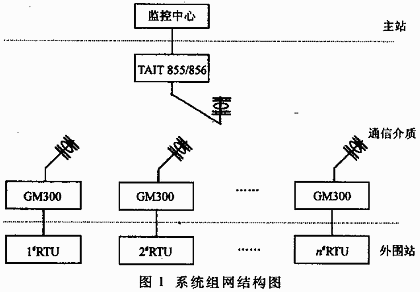
3.1 Composition and function of monitoring center
The control center of the urban street lamp wireless communication SCADA system is mainly composed of the main control machine, backup machine, server, large-screen multimedia projector, radio station, tower and antenna.
The host computer and the server are connected to the network according to the Client / Server structure. As the client of the system, the host computer is composed of an Intel industrial control computer, which is programmed in VB language. The main function is to realize the human-machine interface and connect with the radio station through the wireless Modem, send control instructions to the RTU, and receive the returned test data and status parameters. . In order to improve the reliability of the system, another Intel industrial control computer is used as the backup computer in the system to backup the main control computer.
An IBM server is used as the database server of the wireless communication SCADA system. The data collected by the RTU is processed by the host computer and stored in the data server. Other management systems can access the server directly after authorization. .
The monitoring center mainly completes the following functions:
(1) The large-screen multimedia projector dynamically displays the location of each RTU in the SCADA system on the city map and the working status and real-time parameters of the site (including the AC voltage, current, power, watt-hour reading of each line, Light rate, etc.).
(2) According to the city's longitude correction and sunrise and sunset times, a daily light on / off time curve corresponding to the whole year is drawn to control the on / off of street lights in real time; in addition, the controller can modify the on / Turn off the light time and send it to RTU for control.
(3) Regular inspection / fixed-point detection RTU, and obtain the switch status, data parameters and alarm code returned by RTU through wireless modem.
(4) During the inspection process, if a fault is found or the parameter exceeds the limit, an audible and visual alarm can be performed, and an enlarged map with the site as the main center and the corresponding working conditions, measured data and faults are dynamically displayed on the large screen form.
(5) It has the function of saving energy, and implements two working modes of full night light / midnight light. The control staff decides whether to adopt the midnight light method and adjust the start and end time of the midnight light arbitrarily for each line. At the same time, it also has an anti-theft monitoring function: when the current value of a certain branch is detected to be greater than the normal operating value, if the current value of other branches in the same RTU is normal (indicating that the A / D chip is working normally), there is a problem in the branch Electrical phenomenon.
(6) The virtual meter method is used to display the shape of meters such as voltmeters, ammeters, and watthour meters. The VB control Meter is used to visually display the dynamic changes of the simulated data volume on the dashboard.
(7) Timing all RTUs regularly to ensure the accuracy of the peripheral stations.
(8) Data processing, storage and report printing functions.
3.2 Wireless communication
3.2.1 Communication media
Wireless communication SCADA system monitoring center and RTU use VHF / UHF radio station for data transmission, working frequency is 203 ~ 450Hz (must apply to the local radio management department for the corresponding frequency point), data communication modulation method is FSK, transmission rate 300 ~ 1200bps. The distribution of RTU sites is scattered, and the distance from the monitoring center is far, so the communication system adopts a large-area system. The monitoring center selects the TAIT 855/856 base station with a transmission power of 45W and works in full-duplex mode. The coverage is related to the height of the high-gain omnidirectional antenna tower, and the radius can reach tens of kilometers. RTU uses Motorola GM300 car radio, equipped with a directional antenna, the transmission power is 25W, and works in half-duplex mode.
3.2.2 Communication method
The monitoring center uses broadcast or point-to-point to send commands to the RTU. When using the broadcast mode, the RTU only receives commands and executes them, such as proofreading time, modifying on / off light time and other commands; when using the point-to-point mode, such as telemetry and remote control, the RTU first confirms the station number, if it is executed according to the command format Corresponding operations, such as control circuit is on / off, return current, voltage, switch status, fault code data frame to the monitoring center.
3.3 RTU structure module design of peripheral station
The RTU structure diagram of the peripheral station of the wireless communication SCADA system is shown in Figure 2.
The RTU is mainly composed of a single-chip microcomputer measurement and control system, including data acquisition and processing and A / D conversion circuit, keyboard display circuit, clock circuit, street lamp all night light / midnight light control circuit, and wireless communication circuit. Peripheral stations can operate independently. Even if they cannot contact the monitoring center due to communication failures or other reasons, they can also complete the increasing monitoring of the street light system alone.
The SCM measurement and control system uses 80C31 as the CPU, 27C256 as the EPROM, 62256 as the RAM, 74LS138 is used in the address decoding circuit, P2.7 is respectively connected to the chip select signal of 62256 (for zero selection) and 74LS138 pin G1 (for 1 selection) , P2.4, P2.5, P2.6 are connected to 74LS138 pins A, B, C, respectively, output chip select signal to control multiple switches, ICL7109, DS12887, 74HC245, LCD display.
(1) Data acquisition and A / D conversion circuit
RTU real-time measurement parameters include line voltage, current, watt-hour meter reading, etc. The analog input signal of this module has three-phase AC voltage UA ~ UC. Line total current IA ~ IC, each branch current (this system can detect up to 8 branches) I1A ~ I1C, ..., I8A ~ I8C, the signal passes V / I transmitter, multi-way switch (4051 & TImes; 4 pieces) 3. The signal processing circuit (including the conversion of AC signal rectification and filtering) is sent to the double integral A / D converter ICL7109, which is converted into twelve-bit binary numbers, of which the lower eight bits D1 ~ D8 and P0.0 ~ P0 7 connected, the high four bits D9 ~ D12 are connected with P0.0 ~ P0.3, the CPU reads the high four bits and low eight bits of data from the data bus by controlling the high / low byte enable terminals HBEN and LBEN.
(2) Keyboard display circuit
Using liquid crystal display. The key functions are: setting station number, time, current change value of each branch, current / voltage zero adjustment, all-night light / midnight light mode, patrol / fixed-point detection of each branch parameters, etc.
(3) Clock circuit
The clock chip DS12C887 is used to provide accurate clock signals, including year, month, day, hour, and minute. The time can be modified manually, or the time can be unified by the monitoring center.
(4) Street lamp on / off circuit
The on / off of the street lamp line of this station can be automatically executed by the daily on / off time fixed in the EPROM, or it can be realized by manual setting or remote control by the monitoring center.
(5) Wireless communication circuit
The received analog carrier signal is demodulated into a digital signal by the modulation / demodulation chip TCM3105 and transmitted to the CPU. The digital signal to be transmitted is modulated into an analog carrier signal and data is transmitted through the GM300 car radio, directional antenna and monitoring center. 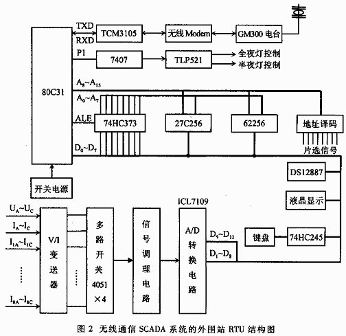
4 Precautions for realization of street lamp wireless communication SCADA system
The urban street lamp wireless communication SCADA system using VFH / UFH radio communication has been operating normally for several consecutive years. Experience has shown that as long as the reliability of data wireless transmission is solved, this method is significantly better than wired transmission in urban large-capacity monitoring systems, with a high performance-to-price ratio, and can easily expand RTU arbitrarily. The author believes that the following aspects need to be noted during the design, commissioning and installation process:
(1) Pay special attention to the field strength test of wireless signals. Before the installation of the peripheral station, the signal is sent by the base station of the monitoring center, and the field strength test should be carried out at each RTU installation place. There should be no obvious co-frequency interference and inter-frequency intermodulation interference, and the signal level should be above 20dB. If an RTU cannot be met, the address must be changed; when most RTUs cannot meet the requirements, the operating frequency of the radio station must be changed.
(2) Cannot select too high communication baud rate, otherwise it is easy to cause code loss.
(3) It is found in the debugging of the A / D conversion circuit that the pins 17 (TEST) and 27 (SEND) of the ICL7109 chip cannot be left floating and should be connected to + 5V with 26 (RUN / HOLD). Otherwise, the A / D conversion data will often be unstable.
(4) The V / I transmitter used to measure the three-phase voltage cannot be directly mounted on the motherboard, otherwise it will be easily damaged by lightning strikes.
(5) If the wireless signal is affected in a mountainous area, an interruption station can be set up.
Automatic Moto,Moto Automatic,Steering Motor,Automatic Steering Motor
Jinan Keya Electron Science And Technology Co., Ltd. , https://www.keyaservo.com