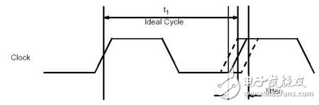
Jitter reflects the time offset of the digital signal from its ideal position. The bit period of the high-frequency digital signal is very short, generally in the hundreds of ps or even tens of ps, and the small jitter will cause the level of the signal sampling position to change, so the high-frequency digital signal has strict requirements for the jitter.
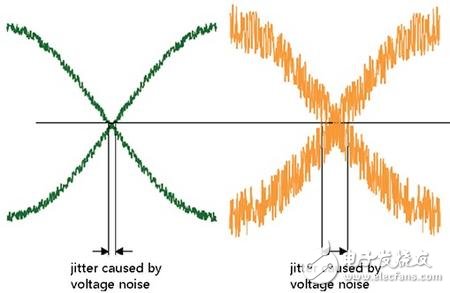
The actual signal is very complex and may have both a random jitter component (RJ) and a deterministic jitter component (DJ) of different frequencies. Deterministic jitter can be caused by inter-symbol interference or some periodic interference, and a large part of random jitter is derived from noise on the signal. The figure below reflects a noisy digital signal and its decision threshold. Generally, we judge the state that the digital signal exceeds the threshold as "1", and the state below the threshold is judged as "0". Since the rising edge of the signal is not infinitely steep, the vertical amplitude noise causes the signal to pass the threshold point. The left and right changes, which is the cause of signal jitter caused by noise.
For signal jitter analysis, the most common tool is a wideband oscilloscope with a response jitter analysis software. The jitter analysis software in the oscilloscope can easily decompose the size and various components of the jitter, but the oscilloscope is difficult to accurately measure sub-ps-level jitter due to noise and measurement methods. Many high-speed chips now require clock jitter below 1ps or even lower. This requires the use of other measurement methods such as phase noise measurement.
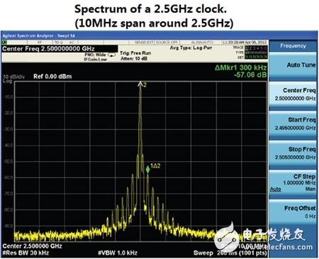
We know that jitter is a time deviation, and it can also be understood as a change in clock phase, which is phase noise. For the clock signal, we observe the spectral distribution of its fundamental wave. The ideal clock signal should have a very narrow spectrum of fundamental waves, but in fact, due to the presence of phase noise, its spectral line is a wider envelope. The narrower the envelope, the phase noise (jitter). The smaller the signal, the closer the signal is to the ideal signal. The figure below shows the spectrum of a real clock signal. The fundamental of the signal is at 2.5 GHz. We observe the spectrum of the 10 MHz bandwidth around 2.5 GHz. We can see that the spectrum of the first signal is not a very narrow spectrum, its spectral line is broadened (the effect of random noise), and the second is superimposed with some specific frequency interference (the effect of deterministic jitter).
In order to make it easier to observe low-frequency interference, in the phase noise measurement, the carrier frequency of the signal is usually used as the starting point, and the abscissa is displayed in logarithm. The abscissa reflects the distance from the signal carrier frequency, and the ordinate reflects the corresponding The ratio of the energy of the frequency point to the energy of the signal carrier. The smaller the ratio, the smaller the energy of the frequency components other than the carrier, and the purer the signal. The instrument used to accurately measure the phase noise of the clock signal is a signal source analyzer. There is a special circuit inside the signal source analysis. The phase noise of the local oscillator can be very low by multiple correlation processing of two independent local oscillators. So that accurate phase noise measurements can be made.
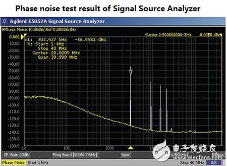
For many clocks generated by crystals, the main component of their jitter is random jitter. If we integrate the phase noise energy of different frequency components in the phase noise test results, we can get random jitter. By measuring the phase noise by the source analyzer and then integrating the energy in a certain bandwidth, we can get accurate random jitter measurements. The minimum jitter that the source analyzer can measure can be up to the fs level.
IP 20 frequency inverter for three-phase asynchronous motors, specially designed for pump and fan applications in the following market segments: Water & Wastewater, Oil & Gas, building management and energy plant.
Three Phases Inverter Elrctric,Period To Frequency Converter,Three Phases Frequency Converter,Wavelength To Frequency Inverter
Wuxi Trenty Machinery & Equipment Co., Ltd. , https://www.elec-inverter.com