At present, the road lighting management system of most cities in China still uses a relatively simple traditional control method such as light control and time control. These systems are generally difficult to feedback the status information of street lights, difficult to control remotely, etc., and the power saving effect is not ideal. In addition, most of the city's street lamps use "all-night light" to illuminate. There are two common problems: on the one hand, pedestrians are scarce in the middle of the night, and the "all-night light" method is too wasteful. Therefore, some places In the middle of the night, the "mid-night light" lighting mode was completely extinguished in the middle of the night; in some places, in the latter half of the night, the power-saving measures of "bright one by one" or "bright one separated by two" were adopted, which saved electricity expenses. It has brought about social security and traffic safety issues, which is not conducive to the image of the city.
1 System Solution Overview The system consists of a lighting area controller and an intelligent node. The lighting area controller is responsible for the intelligent lighting control of the road section under its jurisdiction, while the intelligent node is responsible for the control and status detection of a single street light. Wireless communication is used between the intelligent node and the lighting area controller for data transmission.
The system is to set the output power level by the specific conditions of the road condition, thereby changing the illumination of the street lamp to achieve energy saving. The basic idea is that the street light can adjust the brightness of the light, ie the dynamic dimming strategy, with the speed and number of vehicles or pedestrians on the road. Its working block diagram is shown in Figure 1.
This article refers to the address: http://
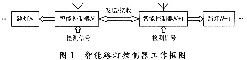
The working process of the intelligent controller 1 is: under the control of the intelligent controller 1, the light intensity of the surrounding environment is detected by the photosensitive element, and an instruction is issued to the power adjusting unit according to the detection result of the photosensitive element to realize the light being turned on and turned on at night. The operation of the street light is off. When the street light is turned on, the radiation detecting unit starts to work. When the vehicle or pedestrian passes through the road, the radiation detecting receiving unit generates an associated pulse signal and transmits it to the controller 1, and the controller passes the pulse signal and the time interval. The software obtains relevant parameters such as the number of vehicles or pedestrians and the speed of travel, and issues relevant instructions to the power adjustment unit to take different levels of light brightness for a period of time. At the same time, the controller 1 passes the relevant parameters to the next one or several microcontrollers via the wireless communication unit.
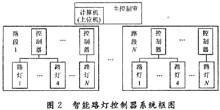
The next MCU that receives the signal will change the brightness level before the person arrives, and the continuous time can satisfy the vehicle or pedestrian passing a certain distance through the lamp. This lamp also detects the passing of the vehicle or pedestrian in real time and passes the relevant parameters to the future. Street light. Each street lamp node communicates with the computer of the main control room to monitor the running status of the street lamp in real time. Its system block diagram is shown in Figure 2.
2 system main unit hardware structure design
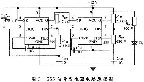
2.1 Moving object monitoring unit The signal generating circuit is implemented by two 555 circuits. The previous 555 is used to generate a 1 kHz modulated signal, which is output by the 3 pin to the next reset terminal 4, and the latter 555 is used to generate the 38 kHz square wave signal. The 4 pin is used as the modulation end, that is, when the 4 pin is high, the 555 is a conventional square wave oscillator; when the 4 pin is low, the 3 pin of the 555 is at a low level. This signal generator and the 38 kHz infrared connection can be used for pedestrian or vehicle detection. The schematic diagram of the circuit is shown in Figure 3.
2.2 Wireless transmission unit The main controller of this system adopts Atmel's ATmegal6, which is a real RISC-structured single-chip microcomputer. It has rich internal resources and integrates various powerful peripheral interfaces and communication interfaces on-chip. In this design, the task of the single-chip microcomputer is mainly to complete the conversion of the mains voltage collected by the step-down processing, complete the judgment of the power-saving level through software, and control the corresponding relay to perform the corresponding on-off action; It is necessary to record the time and status of the switch light during a period of time, and to complete communication with external devices.
The wireless communication module of the system is a single-chip RF transceiver chip nRF905 from Nordic VLSI, which operates from 1.9 to 3.6 V. It is small in size and can work on three ISM channels of 333/868/915 MHz. The output gain is small. The range is -10 to +10 dE, and the maximum wireless data transmission rate is 50 Kb/s. It is suitable for wireless data communication, wireless alarm and security systems. The chip can easily realize the design of the wireless transceiver module through the simple control of the single-chip microcomputer. It exchanges data with the single-chip microcomputer through the SPI port. When working in the slave mode, the clock is determined by the SPI clock of the single-chip microcomputer.
3 system working mode and software design
3.1 System working mode The lighting area controller and the intelligent node realize the data transmission through the nRF905 module, and still adopt the master/slave structure, that is, the lighting area controller gives the control instruction, and the target intelligent node address information is included in the instruction, In the broadcast mode, the intelligent node determines whether to perform the operation according to the node address information in the instruction after receiving the instruction. For a node that needs to be a relay, first determine the control word and the target node address information after receiving the instruction. When it is a single point control or query instruction, if the own address is equal to the target node address, the operation is performed; otherwise, the target node is determined. Whether the address is in the valid range of its own relay, it is relaying the instruction, and vice versa.
3.1.1 Intelligent lighting control strategy design In the absence of human or management center intervention, the lighting area controller completes the autonomous on-site lighting control according to the preset lighting control strategy. In this design, a lighting control strategy combining time control (time control), environmental parameter assist control and manual control is adopted. The environmental parameter auxiliary control is an optional function. When it is forbidden, it is combined with time control and manual control. The priority of the three control methods follows the following principles:
(1) The manual control has the highest priority. When the manual control is performed, the time control and environmental parameter auxiliary control are blocked.
(2) When the manual control is canceled, the environmental parameter auxiliary control and time control are restored to normal use. If the time control is valid, the system maintains/updates the running status according to the time control strategy; if it is outside the time control validity period, it is based on the environmental conditions. control.
(3) When the system exits the manual control mode, the lighting area controller determines the current time period and determines whether each AC contactor is turned on or off.
3.1.2 Environmental parameters and flow control strategy The intelligent road lighting control system should also be able to adjust lighting control measures according to actual environmental parameters such as weather and traffic flow to obtain better lighting quality and power saving effect.
(1) Illumination-assisted control Considering the influence of abnormal weather changes, it is necessary to comprehensively consider the natural environment illuminance and current time, and perform corresponding lighting or turning-off operations. It should be noted that in order to ensure the stability of the system, it is necessary to take measures such as delay or software filtering to eliminate ambient illumination spikes (such as lightning) when collecting ambient illumination. In addition, it should also limit the time period of control according to illuminance or use fuzzy control means to distinguish between interference and normal conditions, and avoid malfunction caused by persistent disturbance of mutation.
(2) Traffic flow assisted control In the intelligent lighting control system to achieve humanized lighting control, we must also consider the abnormal situation of traffic flow changes in the same lighting season, especially in some important holidays, people's work and rest Habits will be different when there is peace, so the road traffic flow curve will be more fluctuating than usual. At this time, it can no longer be controlled according to the normal time period, but must be controlled by traffic flow. Considering that such fluctuations are mainly concentrated in a relatively concentrated time period, it is only limited to be valid for a specific period of time in software design.
3.1.3 Regional Control Strategy The development of wireless communication technology has enabled low-cost single-lamp control and detection, and has also made streetlight control more flexible. Different street lamps on the same road segment may have different lighting control requirements due to their different positions. For example, a streetlight at a crossroads is not able to perform the same scene control at the same time as other streetlights due to the important speciality of the location. In addition, in the case of a multi-lamp, it is necessary to consider partial shutdown when the traffic flow is reduced to save energy. Zone control can be achieved by configuring a communication protocol between the underlying control system (lighting zone controller intelligent nodes). The area control data frame format is as follows:
![]()
The control type declares which control operation should be performed by the single-lamp intelligent controller. The start address, the end address and the scope together declare the address number requirement for the controlled street light node, which is equivalent to binding the street light node that meets the same conditions. Together, regional control can be achieved. The range of action can be divided into odd-numbered and even-number-effective according to the mathematical characteristics of the single-lamp intelligent controller address number, so that a variety of control region combinations can be realized.
3.1.4 Time Control Strategy Time control mainly includes daily switching light control and dimming control at night according to road traffic flow. These control operations should not only achieve significant power savings, but should also improve road lighting quality.
(1) Switching lamp time can divide the year into 12 time segments for one month. The starting and ending time of each month should be based on the specific local sunshine conditions, and the average value after multiple measurements can be used, and the obtained data is saved in the single-chip microcomputer for software inquiry.
(2) Diversified control at night time. Night street lighting control is mainly based on the change of road traffic flow at night, although the traffic flow at different times of the day and night will be slightly different on one road, but the statistics are in a period of time (one month or several months). According to the law, the fluctuation of this change is not very large, so it is completely possible to divide the lighting cycle of one year into several lighting seasons according to the law of average traffic flow variation. Since the switching lights have different time in each lighting season, the whole time of each day is divided into three hours, and each hour can be used for dimming, partial switching or all switching of the street lamps with pedestrian detection.
3.2 System Software Design This paper uses ICCAVR editor, combined with Atmel's AVR Studio integrated development platform for design.
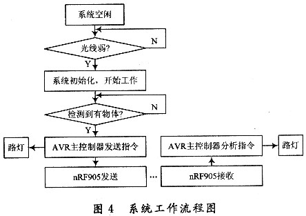
The workflow of the system is shown in Figure 4. The system starts to initialize when the external light reaches the lighting demand, and enters the working state. At this time, the infrared detector will continuously monitor the pedestrian or vehicle on the road and transmit the detected data to the AVR main controller. The main controller will light the street light according to the amount of data, and start to use nRF905 to transmit messages to the next group of street lights. The latter group processes the information in the main controller after receiving the message, lights the street lights ahead of time, and waits for re-monitoring. Go to the object and cycle like this. The software records the opening time, and the corresponding dimming procedure is started when the corresponding divided time period is entered.
The MCU chip and the wireless transceiver chip must be initialized before starting work. The system includes the following two parts:
(1) SPI interface initialization of ATmegal6L. ATmegal6L's asynchronous serial interface and SPI interface use the same USART module, and you must select the SPI master/slave mode, and also ensure that there is only one host in the system. For this system, the AVR microcontroller should be set as the host, and the nRF905 module is set to Slave.
(2) Initial configuration of nRF905. The configuration of the initialization parameters of the wireless transceiver chip is set by the configuration register of the nRF905. The nRF905 has a 144 b configuration word that specifies the wireless transceiver's wireless transceiver operating mode, transmit and receive frequency, transmit frequency, transmit and receive address width, receive address, wireless transmission rate, crystal frequency, and length of the CRC checksum. And valid data length, etc. At the same time, the nRF905 wireless transceiver can only be in one of the working modes. Regardless of whether the mode wants to send or receive data, the module must be initialized after power-on.
When nRF905 transmits data, the system sets TRX_CE through software, and makes TX_EN and PWR_UP high to activate the Shock Burst TM transmission mode of nRF905 to realize data transmission. The Shock Burst TM allows the transceiver chip to be powered up automatically, and data packing (plus headers and CRC checksums) is completed and packets are sent. When the data transmission is completed, the data preparation (DR) pin is set high. If AUTO_RETRAN is set high, then nRF905 will continuously transmit the data packet until TRX_CE is detected to be low; and when TRX_CE is set to low power Normally, it indicates that the nRF905 data transmission has ended and will automatically enter the power saving mode.
When TR_CE is high TX_EN is low, nRF905 enters Shock Burst TM receiving mode; after 650μs, nRF905 continuously detects and waits for data reception; when nRF905 detects carrier in the same frequency band, carrier detect (CD) pin is set high; However, after detecting a matching address, the address match (AM) pin is set high; after that, the packet is received. After the reception is completed, the nRF905 automatically removes the header, address, and CRC check bit, and then directs the DR. The feet are set high. After this, the microcontroller will set TRX_CE low, so that nRF905 is in idle mode; then the microcontroller will transfer data to the microcontroller at a certain rate through the SPI interface; when all the data is received, nRF905 will put the DR pin and The AM pin is set low. The entire receiving process has been completed.
After receiving the information, the MCU will analyze and compare with the existing information, and issue relevant instructions, and then start to enter the next transmission cycle.
4 Conclusion The intelligent street lighting control system uses a variety of control methods to manage the status and brightness level of the street light switch with local specific time periods, and uses the radio frequency communication technology to realize the regional control and real-time information exchange of the road segment to achieve "chasing light" illumination. It is equipped with an automatic fault alarm function, and it reduces operating and maintenance costs. The system is easy to use, reasonable in manufacturing cost, and easy to maintain. In general, it has broad prospects.
relay fuse box,12v relay box,car relay box
Dongguan Andu Electronic Co., Ltd. , https://www.idofuseholder.com