As a solid-state light source, light-emitting diodes (LEDs) have been widely used due to their long service life, excellent efficacy, and environmental characteristics. Currently, LEDs are replacing existing lighting sources such as incandescent lamps, fluorescent lamps, and HID lamps. To light the LED, it needs to operate with a constant current and must have a high power factor. In addition to the latest EnergyStar® directive for solid-state lighting that requires lighting sources with power above 3 W to have a power factor greater than 0.9, ballast input line current harmonics also need to meet the requirements of the IEC61000-3-2 Class C specification.
To meet these LED lighting application requirements, a single-stage flyback converter with integrated PFC is typically used in low-power (25 W) LED lighting applications. In addition, the primary-side regulation (PSR) flyback circuit is the most cost-effective solution in a variety of flyback topology circuits. By using a single-stage topology with primary-side regulation (PSR), LED lighting circuit boards do not require input electrolytic capacitors and feedback circuitry and can be implemented with very few external components, thereby minimizing cost. Figure 1 shows a single-stage PSR flyback LED driver circuit.
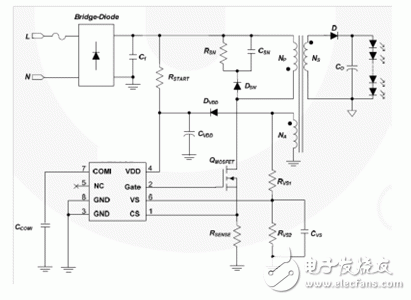
Figure 1: Single-Stage PSR Flyback LED Driver with High Power Factor
For primary-side regulation, discontinuous conduction mode (DCM) is usually preferred because it provides very accurate output regulation [1]. In order to achieve high power factor and low total harmonic distortion (THD), constant on-time control is often used in DCM flyback converters with a fixed switching frequency. Figure 2 shows typical theoretical waveforms for the primary side switch current, the secondary side diode current, and the MOSFET switch gate signal.
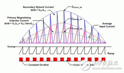
Figure 2: Timing and Input Current of DCM Flyback PFC Converter
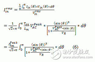
Under the condition that the conduction time is constant, the average input current is as follows:
Here, D is the switching duty cycle of the converter and is the primary winding inductance of the flyback transformer. The above equation shows that the input current waveform always follows the input voltage. Therefore, the converter implements a unit power factor.
Then, the RMS input current can be calculated by:
For inputting the MOSFET's turn-off transient inductor current when the AC voltage reaches its maximum value.
In order to maintain the DCM operating mode, the maximum duty cycle D must satisfy [1]:
The voltage at the primary side of the transformer when the secondary diode conducts.
To ensure that the flyback converter operates at unity power factor in DCM mode and has low THD performance, a transformer with a relatively small turns ratio is often used. This type of flyback transformer results in a smaller switching duty cycle, which increases the peak value and RMS current flowing through the MOSFET switch and transformer, resulting in more power loss. Because of the high peak switching current, relatively large EMI filters are needed.
Flyback converters with critical conduction mode (BCM) have zero voltage turn-on characteristics to minimize switching losses and are therefore often used as single-stage PFC converters. The working principle of a single-stage PFC flyback converter with BCM operation mode is described in "References" [2]. Unlike the DCM operation mode, the BCM flyback method is controlled by a constant on-time and a variable switching frequency. The BCM flyback method for PFC is suitable for many applications where relatively high PF is required but the total harmonic distortion (THD) is not less than 10%. Figure 3 below shows the theoretical waveforms for the primary side switch current, the secondary side diode current, and the MOSFET gate switching signal.
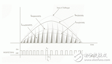
Figure 3: Timing and Input Current of BCM Flyback PFC Converter
As detailed in "References" [2], the average input current is expressed as follows:
Unfortunately, the denominator in the input current equation above makes the current waveform exhibit a distinct non-sinusoidal shape unless the ratio is very small. Figure 4 below shows the input current waveform of the BCM flyback topology, where RVR is the parameter [2]. Harmonic analysis of the input current waveform shows that if the RVR is 2, it is difficult to obtain less than 10% THD.
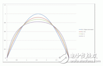
Figure 4: BCM Flyback Topology Input Current Waveform with RVR as Parameter
During the off period of the switch, the maximum voltage on the switch is equal to the peak input voltage plus the reflected voltage VR. Therefore, due to the MOSFET switch's rated voltage limit, the possible value range of RVR is only 1 (US standard input voltage) and 2 to 3 (standard European input voltage). For lighting applications with a universal input voltage, in order to achieve relatively low THD, 800 V or even 1000 V MOSFETs must be used to keep the RVR ratio as low as possible. Its switching frequency can also become very high, especially in LED dimming applications with high input AC voltage.
After carefully reviewing the above expression, the following conclusions can be drawn:
1. The reference voltage for the MOSFET peak drain current is not required as a reference. If the on-time is constant during the half cycle, the peak drain current will change with the input voltage.
2. The main reason for the unsatisfactory input current waveform is the variable frequency, more precisely the variable duty cycle. With the same drain current waveform, the input current will be sinusoidal if the duty cycle remains constant during the half cycle.
The hydrogel Screen Protector has super ductility and shrinkage, has a strong and effective self-repair function, impact resistance, durability, better toughness, and has a certain buffering effect on sharp objects. The use of hydrogel film can adapt to the contours of any device, so it can be attached to curved screens and rounded edges. The full-coverage screen protector can perfectly fit your screen and provide maximum protection.
The 0.14mm ultra-thin thickness is more sensitive to the touch, and the ultra-thin design gives you a bare-metal experience. The oleophobic and waterproof coating prevents fingerprints and dust, makes the hydrogel screen protector easy to clean, and makes your phone look more beautiful.
Hd Clear Hydrogel Protector Sheet,Anti Blue-Ray Hydrogel Protector,Matte Hydrogel Film,Privacy Hydrogel Film
Shenzhen TUOLI Electronic Technology Co., Ltd. , https://www.szhydrogelprotector.com