0 Preface
There are many ways to test the power supply stability. In the development of the transmission electron microscope of the 220 kV field emission gun, the stability of the coil constant current power supply is very high, especially the constant current power supply of the objective lens coil, and the coil current stability reaches 2 ppm/min. A reliable, convenient and efficient power stability test system to work. At present, the high stability test system often uses the recorder method, but its operation is inconvenient and the precision is not high.
According to the needs of the project work, the author developed a practical online automatic test system for coil power supply with high stability based on Lab-VIEW virtual platform. Taking the objective coil coil power supply current stability test as an example, this paper introduces the composition, measurement principle and software programming of the system, and gives the data processing method and measurement results.
1 test system hardware composition and principle
1.1 System components
The test system consists of the structure shown in Figure 1. The coil power supply supplies current to the coil and the sampling resistor R. The 8-bit half-digital multimeter collects the voltage signal on the sampling resistor R. The voltage digitized data is input to the computer via the GBIB interface. Analyze processing and display in real time.
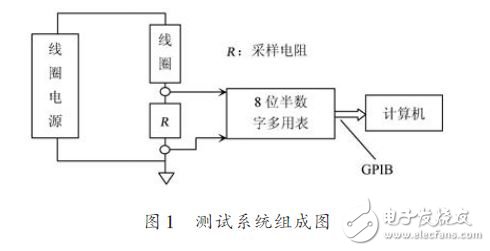
The system's digital multimeter uses the Agilent 3458A multi-purpose digital multimeter. The 3458A DC voltage profile features: up to 8.5 bit (28 A/D) resolution, maximum sensitivity of 10 nV; 0.6 ppm / 24 h accuracy, 8 ppm/year voltage reference stability. The coil power supply has the highest stability for the objective lens coil power supply and requires a coil current stability of 2 ppm/min, so the 3458A digital multimeter can meet the requirements.
The data acquisition process of the system is: The digital multimeter 3458A has a standard GPIB interface, which is converted into a standard USB interface by the 82357B module, so that it can be easily connected to the computer.
1.2 Stability test method
According to the national standard "JB/T 9352-1999, Transmission Electron Microscopy Test Method", the stability of the coil power supply is defined as the ratio of the amount of change in the sampling voltage to the average value of the time voltage within a certain period of time. In the above system composition diagram, the sampling resistor is a very stable metal film resistor and is placed in a constant temperature tank, so the voltage of the sampling resistor can truly reflect the condition of the coil power supply.
The test process is: let the coil power supply work stably for a period of time, continuously record the sampling voltage, and then take out the continuous record for 10 minutes to compare the stable data, with a calculation interval of 1 min, 10 intervals for 10 min, calculate the interval of each interval. Sampling the amount of voltage change, and then calculating the arithmetic mean of the voltage variation of 10 intervals, specifically calculating the minute voltage stability of the coil power supply according to equation (1):

Where: Sa is 1 min voltage stability; ΔVSV is the 10 arithmetic mean of the sample voltage change per minute; VSV is the nominal value of the sample voltage.
2 system software design
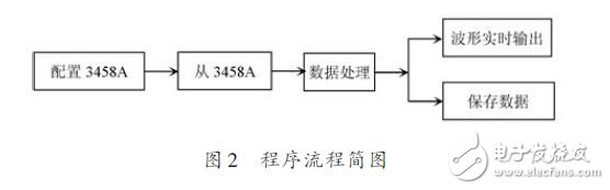
The system is developed under the LabVIEW 8.5 environment of the virtual instrument development platform. The main functions of the program are: configuring the 3458A digital voltmeter, reading data from the voltmeter, real-time graphic display of data, and file storage of data. The system is designed to store data as. The txt file format can be processed later by software Excel. The schematic diagram of the program flow is shown in Figure 2.
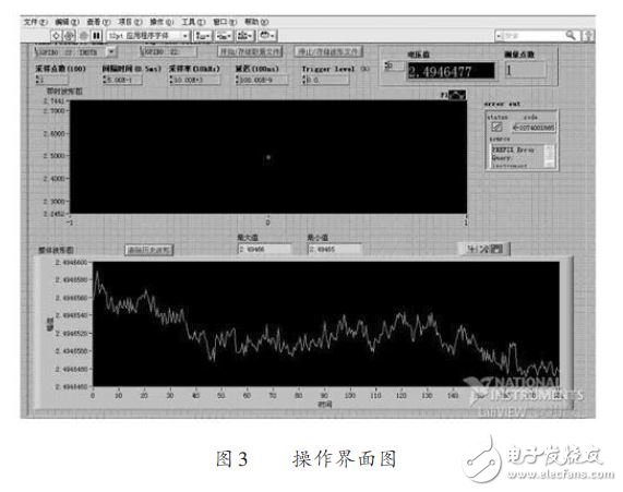
The designed acquisition program interface is shown in Figure 3. When you click Start, set the number of sampling points per second and the interval time (integration time). Click to start storing the file and start collecting data display and storage. The measured voltage information can be obtained from the instant waveform map and the overall waveform graph.
2.1 Configuring the Programming of the 3458A
The communication between the computer and the 3458A in this system is done using the VISA function of LabVIEW. The relevant features are as follows:
VISA is a single-interface library that controls VXI, GPIB, RS 232, and other types of instruments on all LabVIEW work platforms. With the VISA standard, the time and instrument I/O options are not considered, and the driver software can be used interchangeably with each other. Remote operation of the 3458A consists of three parts: reading or changing the GPIB address, issuing commands to the multimeter, and reading from the multimeter. For the normal use of the 3458A functions, the 3458A must be configured as necessary.
2.1.1 Initializing 3458A
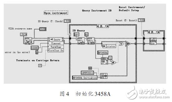
First configure the GPIB address. Usually the reserved address of the 3458A is 22 by default. You can set its address to: GPIB0::22::
lNSTR; Secondly, test whether the 3458A is properly connected to the computer. If the 3458A is commanded "ID-", the instrument will return "HP3458A", so it is convenient to know whether the 3458A is normally connected to the computer. The block diagram is as follows. Figure 4 shows.
Silicon Controlled Rectifier (SCR) is short for silicon controlled rectifier. SCRs are available in one-way, two-way, turn-off, and light control types. It has the advantages of small size, light weight, high efficiency, long life, easy control, etc. It is widely used in occasions such as controllable rectification, voltage regulation, inverter, and non-contact switches and other automatic control and high-power electric energy conversion.
Silicon Controlled Rectifier (SCR)
Silicon Controlled Rectifier,Scr Silicon Controlled Rectifier,3 Phase Silicon Controlled Rectifier,Semiconductor Silicon Controlled Rectifier
YANGZHOU POSITIONING TECH CO., LTD. , https://www.yzpst.com