Design of a cost-effective electric window controller
Abstract Combined with the project practice of car door control module design, a high-performance intelligent power chip TLE7810 is introduced, and its application in low-cost electric vehicle controllers is elaborated in terms of software and hardware. Finally, the anti-trapping function of power windows and its implementation method are briefly introduced.
Keywords Smart Power Chip TLE7810 Anti-Pinch
With the increasing popularity of automobiles, consumers' requirements for automobile comfort are also increasing. More and more cars choose to use the single-chip microcomputer as the core power window control system. In the past decade, the continuous development of semiconductor technology and embedded systems has enabled manufacturers to fully meet the requirements of consumers for the safety and comfort of electric window shakers at a lower cost. The electric windows controlled by the single-chip microcomputer can realize the recognition and protection of various states of the door. In addition, the use of single-chip microcomputer can carry out pulse width modulation (PWM), the use of PWM motor drive mode can extend the service life of the motor, and improve the performance of the window lift, reduce operating noise. Network bus systems such as CAN and LIN enable the car's modular design and interactive communication between modules.
Today, a new generation of smart power devices is quietly emerging. This type of power device combines the control function of the single chip microcomputer and the driving capability of the power device, on the one hand, it reduces the production and design costs of the controller, on the other hand, it makes the circuit more compact and improves the electromagnetic compatibility performance of the controller. This article combines the project practice of car door control module design, introduces a low-cost power window hardware and software design based on the intelligent power chip TLE7810, and briefly introduces the anti-trap function of the power window.
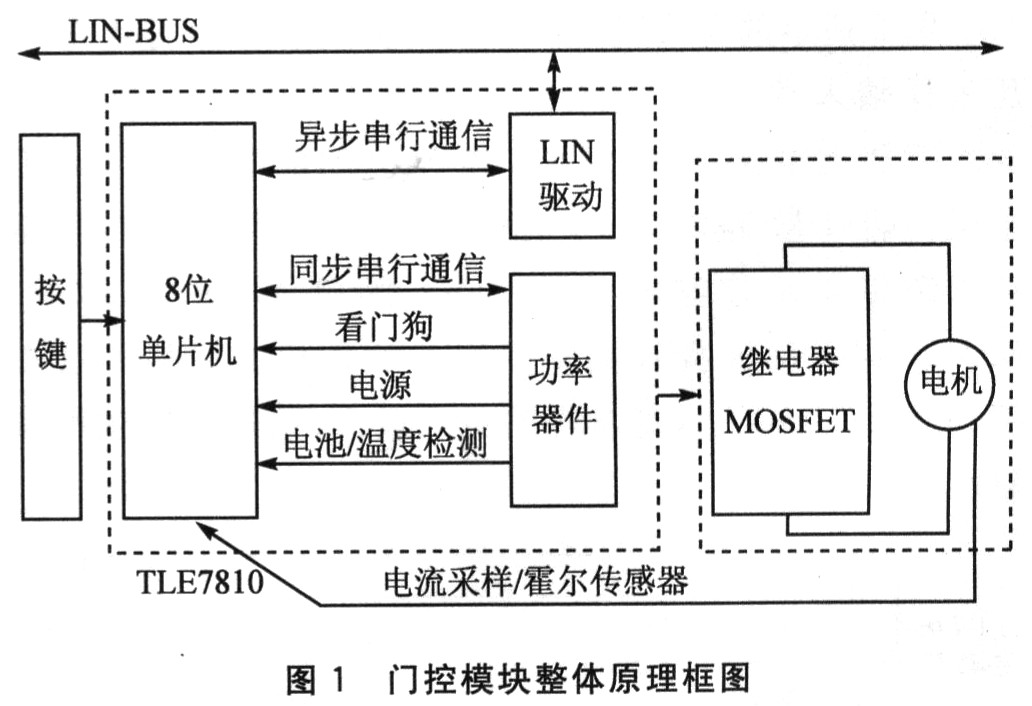
1 The overall design of the car door control module Figure 1 is the functional block diagram of the car door control module. The intelligent power device TLE7810 integrates an 8-bit microcontroller, a power device and a LIN bus driver. The two low-side switches of TLE7810 can be used to control the primary coil of the relay, and then control the H-bridge composed of the relay to realize the forward and reverse rotation of the motor, that is, control the rise and fall of the window. On the other hand, the PWM signal generated by the single-chip microcomputer can control the fast switching of the insulated gate field effect transistor (MOSFET) connected to the grounding terminal of the window motor loop, thereby controlling the switching of the motor loop, avoiding the time when the motor is just started The full-load operation is also called the soft start of the motor, and the voltage PwM control is realized at the same time. In addition, the current sensor and the Hall effect sensor can also feed back the running state and running position of the motor to the single-chip in a timely manner, ensuring the robustness of the system operation (see Figure 3).
2 Hardware design of power windows
2. 1 logic control and external communication The power device TLE7810 integrates an 8-bit single-chip chip, a power device chip and a LIN bus driver chip. It is precisely because the TLE7810 has such a highly integrated structure that it almost assumes all the logic control and circuit driving tasks of the entire controller. The TLE7810 has a total of 28 pins, which are connected internally through a synchronous serial port (SPI).
The 8-bit microcontroller embedded in the TLE7810 is developed based on the standard 8051 architecture, which increases system peripherals and improves the computing power of the processor. It can sample signals such as motor current and battery voltage in real time, receive fault signals and judge the window operation status. The single-chip microcomputer sends commands to the power device through the high-speed SPI, and receives diagnostic information from the power device. At the same time, the asynchronous serial communication interface of the single-chip microcomputer is connected to the LIN driver chip of the power device, and then connected to the external LIN bus to communicate with other modules to ensure driving safety.
The power device inside TLE7810 is very powerful. It includes:
â—† Drive power supply of single chip microcomputer and Hall sensor;
â—† Receive the SPI command from the microcontroller, control the action of two low-side switches and one high-side switch, and return diagnostic information through SPI;
â—† Five wake-up inputs;
â—† Watchdog timer to control MCU reset;
â—† Temperature / power voltage sensor;
â—† LIN driver chip.
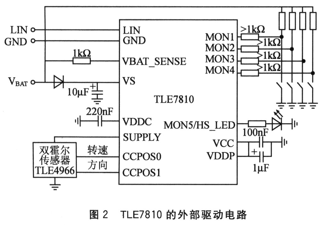
2. The driving circuit of 2 power chips Fig. 2 shows the external circuit of TLE7810. VS is the power supply voltage sampling input port. A 1: 8 operational amplifier circuit is integrated inside the TLE7810 chip, which can perform A / D sampling on the voltage between O and 40 V. Port MON5 is a high-side switch, which can be used as the driving power of LED to indicate the working status of the controller. Ports MONl, MON2, MON3, and MON4 are connected to buttons that control the operation of the windows. In some states, the TLE7810 will enter a low-power sleep mode, and these buttons can wake up the system.
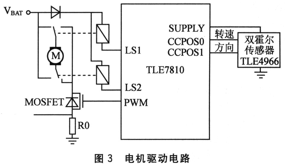
2.3 Motor drive circuit Figure 3 is the motor drive circuit of the window controller. Because the current output by TLE7810 is not enough to directly drive the window motor, the low-side switch of TLE7810 drives the relay, and then the H-bridge composed of relays controls the window to rise or fall. A MOS-FET is connected in series with the ground terminal of the relay, and the PWM waveform control generated by the 8-bit single-chip microcomputer capture and comparison module can realize the soft start of the motor, improve the motor performance and extend the motor life.
2.4 Motor Speed ​​and Current Sampling An O. is connected in series on the lower side of the H bridge that controls the motor. A sampling resistor of 01Ω, the voltage of the sampling resistor is connected to the A / D conversion input port of the single-chip microcomputer through an operational amplification circuit with an amplification ratio of 21 times to detect the current when the motor is running and identify the status of the motor's stall, open circuit and short circuit . Since the accuracy of the A / D converter inside the TLE8710 is 10 bits, the calculation formula of the corresponding current is as follows:
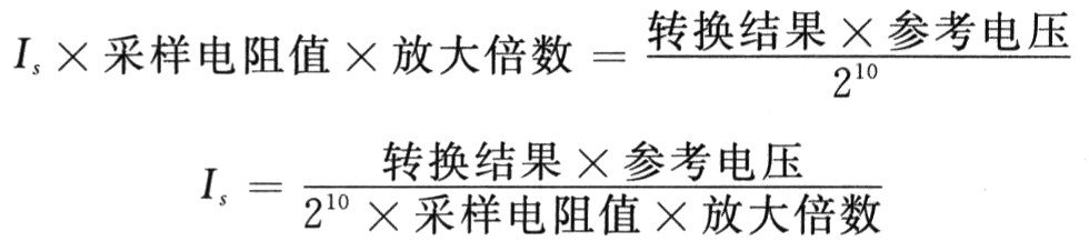
Therefore, assuming that the motor stall current is 10 A and the reference voltage is 5 V, when the sampling result is greater than 430, it can be considered that the motor stalled. For the purpose of protecting the motor, the program will automatically turn off the power and the motor enters the inertial braking state.
In addition, in order to realize the anti-pinch function of the window, the controller uses a dual Hall sensor TLE4966 to determine the position of the window and the motor speed. A magnetic ring with a diameter of about 2 cm is installed on the upper end of the rotor shaft of the motor. The PCB board of the window controller is designed like a pistol. There is a protruding part about 3 cm long on the lower side of the PCB board. A Hall sensor is placed on the top of it to insert it into the motor so that it can be close to the magnetic ring. , Measure the position and speed of the motor using the Hall effect. When the motor rotates, the magnetic ring also generates an alternating magnetic field. Every time the rotor makes a revolution, the Hall sensor outputs a periodic square wave signal. The comparison and capture module of the single-chip microcomputer generates an interrupt when the falling edge of the Hall signal arrives, and records the value of the time register at this time. Using the difference between the two values ​​before and after, the cycle of the square wave signal can be calculated to obtain the motor speed .
Due to the high integration and specificity of TLE7810, the entire system circuit is simple and reliable. The number of chips used here is extremely small, and the EMC performance of the controller has also been greatly improved.
3 software design of power window The program uses a 16-bit timer with automatic reload function as the main timer, the timer overflows every 20 ms, and the interrupt service program sets the 20 ms flag. In the main program, the single chip microcomputer continuously inquires the flag bit of the timer, periodically executes tasks such as A / D sampling, scanning command ports, calling motor control functions and LIN communication.
3.1 Control of the window motor As shown in Figure 4, after the program is initialized, the motor enters the off state. After the key port scans for the control command input by the rising (or falling) key, the main program calls the motor control function, and the motor enters the PWM soft start. The PWM start is divided into 10 steps, each step time is 20 ms, and the duty cycle is gradually increased from 10% to 100%. Then the motor enters the up (or down) state. If the controller receives a stop, descend (or ascend) command at this time, or a stall occurs, the motor enters the inertial braking phase of 200 ms. At this time, the PWM duty cycle is 0, and the MOSFET is turned off. After the end of this phase, the motor enters the rising (or falling) stop state. If you press the key to stop, descend (or rise) command at this time, the motor enters the off state.

If the sampling current exceeds the limit value of short-circuit protection during the rising (or falling) process, it is considered that a short-circuit fault has occurred at this time, and the motor will directly enter the rising (or falling) stop state to prevent the motor from being burned due to excessive current. .
If the current is far less than the normal running current during motor operation, it can be judged that an open-circuit fault has occurred. This information will be fed back to the host computer through the LIN bus, so that the fault can be easily diagnosed and eliminated.
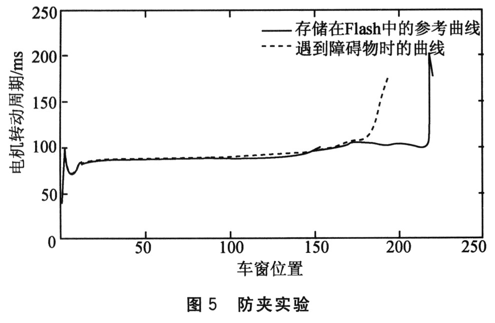
3.2 Anti-pinch function of the window In order to prevent the accident of pinching the passenger when the window is automatically raised. The anti-trap function is designed in the controller. When the window glass runs in the anti-pinch area (200 to 4 mm from the top), the program calculates the motor speed according to the signal of the Hall sensor to determine whether the window meets an obstacle. If it encounters an obstacle, it will issue a descent command to realize the protection function. The results of the anti-pinch experiment are shown in Figure 5.
Conclusion This power window controller uses Infineon's new generation of intelligent power devices, making full use of on-chip resources and reducing system design and production costs. The short circuit, open circuit detection function and anti-pinch function of the controller also improve the driving comfort, improve the reliability of the system, and ensure driving safety.
Features and Benefits of 3 Phase Filter:
It is suitable for 3 phase 3 line power supply.
This kind of Power Noise Filter has a compact structure and the installation is simple and time-saving, especially suitable for applications with limited space, as well highly cost effective.
FT310 series 3 Phase FRF filters are one-stage common mode general purpose 3 phase 3 line filters.
Excellent common and differential mode filtering effect for interference from 150KHz to 30MHz.
520VAC or 690VAC high voltage versions optional.

Power Noise Filter,3 Phase Filter,AC 3 Phase Filter,3 Phase RFI Filter
Jinan Filtemc Electronic Equipment Co., Ltd. , https://www.chinaemifilter.com