There are at least three options for input channels: Channel 1 (CH1), Channel 2 (CH2), and Dual Channel (DUAL).
1) When channel 1 is selected, the oscilloscope only displays the signal of channel 1.
2) When channel 2 is selected, the oscilloscope only displays the signal of channel 2.
3) When dual channel is selected, the oscilloscope displays both the channel 1 signal and the channel 2 signal.
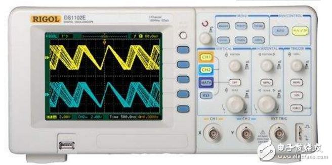
When testing the signal, first connect the ground of the oscilloscope to the ground of the circuit under test. According to the selection of the input channel, the oscilloscope probe is inserted into the corresponding channel socket, the ground on the oscilloscope probe is connected with the ground of the circuit under test, and the oscilloscope probe contacts the measured point. There is a two-position switch on the oscilloscope probe. When this switch is set to the "&TImes;1" position, the measured signal is sent to the oscilloscope without attenuation. The voltage value read from the screen is the actual voltage value of the signal. When the switch is set to the "&TImes; 10" position, the measured signal is attenuated to 1/10, and then sent to the oscilloscope. The voltage value read from the screen is multiplied by 10 to be the actual voltage value of the signal.
Second, the oscilloscope input coupling methodThere are three options for input coupling: AC (AC), Ground (GND), and DC (DC).
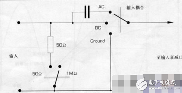
1, input coupling method analysis
1) Ground (GND)
When "Ground" is selected, the scan line shows the position of the "Oscilloscope" on the screen. At this point, the input signal and the attenuator are disconnected and the attenuator input is connected to the oscilloscope's ground level. When ground is selected, a line at 0V level will be seen on the screen. A position control mechanism can then be used to adjust the position of this reference level or scan baseline.
2) Communication (AC)
AC coupling is used to observe AC and AC signals containing DC components. In digital circuit experiments, the "DC" mode is generally selected to observe the absolute voltage value of the signal. In the AC coupling mode, a capacitor is connected in series between the BNC terminal and the attenuator. Thus, the DC component of the signal is blocked and the low frequency AC component of the signal is also blocked or greatly attenuated. The low-frequency cutoff frequency of the oscilloscope is the signal frequency that the oscilloscope displays when the signal amplitude is only 71% of its straight real amplitude. The oscilloscope's low frequency cutoff frequency is primarily determined by the value of its input coupling capacitor. The oscilloscope's low frequency cutoff frequency is typically 10 Hz.
3) DC (DC)
DC coupling is used to determine the absolute value of the signal DC and to observe the very low frequency signal. The DC coupling mode provides a direct connection path for the signal. The signal therefore provides a direct connection path. Therefore, all components of the signal (AC and DC) affect the waveform display of the oscilloscope.
Insulated Copper Tube Terminals
Insulated Copper Tube Terminals,High quality insulated terminal,copper tube terminal
Taixing Longyi Terminals Co.,Ltd. , https://www.lycopperterminals.com