In today's society, automation devices are ubiquitous, and the control theory itself has made significant progress under the impetus of control technology. The monitoring and control of the water level of the water tower no longer requires manual operation. Practice has proved that automated operation has irreplaceable application value. The water level water level automatic controller has the function of adapting to the detection and control of various liquid liquid levels. The pros and cons are analyzed in the design, and the resistance values ​​of various liquids are considered, which are products that can be put into actual production.
1 Design analysis:
The "water tower water level automatic control system" is controlled by a water pump, and the container is a water tower or a liquid storage tank. The water level is normally controlled between C and D, as shown in Figure 1(a). When the water level is below C, the pump starts to enter the water, as shown in Figure 1(b). When the water level is higher than the D point, the pump stops entering the water, as shown in Figure 1(c). When the water level is lower than point C and reaches point B, it will alarm and take the manual start pump, as shown in Figure 1(d). When the water level exceeds D point and reaches the E point, the upper limit alarm occurs, and the pump is forcibly stopped, and the water level flows out from the overflow port, as shown in Fig. 1(e).
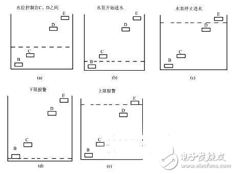
Figure 1 Schematic diagram of design analysis
In order to accurately control the water level, a closed loop control system must be established. According to the water level of the inlet and outlet water in the water tower, the water pump can be automatically controlled to make the water level in a dynamic equilibrium state.
2 Analysis of existing design options:
(1) Automatic water level controller consisting of 555 timers. As can be seen from Figure 2, the circuit design is too simplistic and does not take into account the exclusion of abnormal conditions. For example, if the probe fails, the system cannot be detected, resulting in abnormal operation of the water level controller; no alarm circuit is designed, and the actual value of the water level cannot be conveniently read.
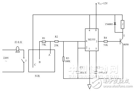
Figure 2 Water level automatic control system
(2) Automatic water level control system designed with 51 single-chip microcomputer. 51 single-chip microcomputer is actually a small micro-machine, in addition to the lap of the hardware circuit, it also needs the development and application of software. This makes the design cumbersome, and from the perspective of electromagnetic compatibility, the software design is systematically unstable. In practical applications, in order to meet the actual conditions of the factory, most of the automation control devices use pure hardware circuit design. In addition, the circuit is unable to detect the conductivity of the liquid and is not suitable for changes in the nature of the liquid in the water column.

Figure 3 Water tower water level control circuit
3 optimal solution:
3.1 System Block Diagram
The control system is mainly divided into two parts: analog detection and logic judgment. As shown in Figure 4, the analog test actually measures the potential of the four probes B, C, D, and E relative to the point A (ie, ground), and the four probes B, C, and D in the clear water in the water tower. The point between E and the point of probe A is actually equivalent to a variable resistor. When the resistance value changes, the potential values ​​of the points are different, and by logical judgment, different outputs are obtained, that is, the operation controls different actions.
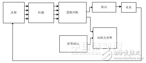
Figure 4 system block diagram
3.2 Schematic
Figure 5 is a schematic diagram of the optimal solution. As shown in the figure: the water level should be between C and D under normal conditions. At this time, the logic level of the four probes of BCDE is 0011, that is, the hold state; when the water level is lower than C, between B and C, The logic level of the four probes of BCDE is 0111, that is, the water inlet state; when the water level is higher than D point, between D and E, the logic level of the four probes of BCDE is 0001, that is, the stop state; when the water level is low At point B or the water level is higher than point E. At this time, when the logic level of the four probes of BCDE is 1111 or 0000, the alarm circuit of the water level of the water tower starts to work, generating a lower limit alarm or an upper limit alarm, that is, under-reporting and over-reporting. At this time, the staff needs to manually close the alarm device to release the alarm.
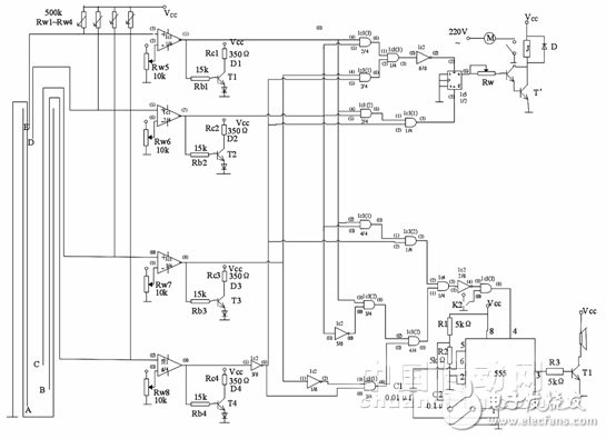
Figure 5 Final connection diagram of the water tower water supply system
3.3 System Optimization
As can be seen from Figure 5, each of the four probes B, C, D, and E is connected to an operational amplifier. In actual operation, when a probe fails, the system can detect it in time without causing malfunction. At the same time, an alarm confirmation circuit has been added. Thus, when a malfunction occurs and the water level in the water tower is too low or too high, an alarm device is activated. Once the system has an alarm, it can be processed in time. After the problem has been solved, the staff can manually turn off the alarm. Therefore, the optimized solution enhances the reliability, stability and practicability of the system.
4 Feasibility test of water tower water level controller
4.1 Feasibility test
Figure 6 is a front elevational view of the water level controller of the water tower, consisting of a power indicator, an alarm confirmation light, a water level indicator, and an alarm confirmation switch. When the power is turned on, the power indicator lights up. When the water depth in the water tower is at different positions, the water level indicators B, C, D, and E are different.
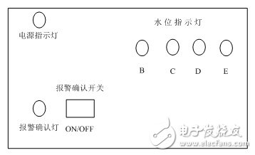
Figure 6 Water tower water level controller appearance
1 When the water level is below point B, the indicators B, C, D, and E are all on, and the alarm circuit starts to alarm, that is, the lower limit alarm.
2 When the water level is between B and C, the indicator light B is off, C, D, and E are on, and the water pump starts to enter the water.
3 When the water level is between C and D, the indicators B and C are off, C and D are on, and the state is maintained, that is, the water is kept.
4 When the water level is between D and E, the indicators B, C, D are off, E is on, and the state is stopped, that is, the pump does not work.
5 When the water level is above E, the indicators B, C, D, E are all off, the pump does not work, the alarm circuit begins to overflow alarm, that is, the upper limit alarm.
6 The alarm circuit can be manually turned off. As long as the alarm confirmation switch is pressed, the alarm beep can be cancelled. At this point, the alarm confirmation light is on. When the fault is processed, the alarm confirmation light must be turned off, the alarm confirmation circuit is reset, and its function of monitoring the fault is restored.
4.2 Feasibility analysis
This scheme adopts pure hardware circuit design, which avoids unstable factors in software program design and improves reliability in practical application. At the same time, this system has good compatibility for different types of liquids. When the liquid in the water tower changes, it is convenient to adjust the water level control operation of the liquid only by adjusting the resistance value in the potentiometer and the resistance value of the liquid to an order of magnitude. The test proves that the water level controller of the water tower not only realizes the precise control of the water level of the water tower, but also the practicality of industrial production.
5 Conclusion
This paper systematically expounds the design scheme and finished product test by introducing the self-designed water tower water level controller. Tests have shown that the system is highly stable during operation and fully complies with pre-specified standards. It is a water tower water level controller that can be put into production.
10.1 Inch Laptop,win10 Laptops,win11 Laptops
Jingjiang Gisen Technology Co.,Ltd , https://www.jsgisentec.com