The water level control switch is a feedback liquid level position signal, informs the center console of the duty room, whether the water level reaches the specified water level, and can control the related equipment to start or shut down (for example, a water pump). The signal voltage is often a 12V or 24V safe voltage.
Water level control switch - application fieldWidely used in industrial boilers, civil construction pools, water towers, water tanks, and open or closed storage tanks in petrochemical, paper, food, sewage treatment and other industries, liquid level measurement of various liquids in underground tanks, medium to be tested It can be divided into various conductive and non-conductive liquids such as water, oil, acid, alkali and industrial sewage. It is combined with an electric valve to form an advanced liquid level display and control device to automatically open and close the electric valve.
Water level control switch principle - capacitiveCapacitive water level switch principle: It is the change of the small capacitance (usually PF) caused by detecting the change of water level. The signal processing is performed by the dedicated ADA capacitance detection chip, which can output various signal communication protocols, such as: IO , BCD, PWM, UART, IIC..., the biggest advantage of capacitive water level detection is that it can detect the change of water level or liquid in the container through any medium, which greatly expands the practical application and effectively avoids the stability of the traditional water level detection mode. The drawbacks of poor sex and reliability, and even problems that cannot be detected in some special areas. The dedicated ADA capacitance detection chip can realize many special control functions due to the built-in MCU dual-core processing, and even realize more integrated and intelligent water level detection functions, such as water level changes after power failure in applications such as solar water heaters and coffee makers. It can reliably detect the current water level. Capacitive water level detection is the most advantageous detection method in the current water level switch.
Water level control switch principle - electronicThe principle of electronic water level switch: (not the electrode type, not by the conductivity of water to judge the water level, the conventional size is 150 & TImes; 20mm) The water level is detected by the built-in electronic probe, and then the signal detected by the chip is processed. When it is judged that there is water, the chip outputs a high level of 24V or 5V, etc. When it is judged that there is no water, the chip outputs 0V. The high and low level signals are read by PLC or other control circuit boards, and the electric water pump and other electrical appliances are driven. The product can be installed in any direction. When installed horizontally, the water level will reach the blue line and the accuracy will be high. When the product is installed vertically, the water level will move when it reaches the red line, and it has a certain anti-wave function. The BZ2401 in the figure is a common type electronic water level switch, suitable for normal temperature water environment. The product is sealed with epoxy resin, sealed and waterproof, can be immersed in liquid for a long time, no mechanical moving parts on the outside, and has a long service life. Electronic water level switch is suitable for industries: waterworks, valuable aquaculture, plant breeding, reservoirs, power supply rooms, sewage treatment industries, etc. Installation method: The same water level switch can be installed freely in horizontal, vertical and diagonal installations, which is flexible and convenient. Fixing method: easy to use, can be fixed by threaded interface (M20) or clamped by pipe clamp. The electronic water level switch can also cooperate with the controller to realize automatic control of the water level and strong anti-wave function.
Water level control switch principle - electrode typeElectrode type water level switch principle: The electrode type water level switch consists of a primary electrode type sensor and a secondary controller. The liquid level switch is installed on the top of the container or on the wall of the container, and the electrode is inserted into the liquid. The single-electrode supply type control is used as a column. When measuring, the electrode has an AC signal voltage. When the liquid level rises and contacts the electrode, an AC signal current flows between the electrodes to generate a liquid level signal. After the control board receives the liquid level signal, it rectifies, filters, and amplifies. After processing, it is finally converted into a relay closed contact output or a standard current 16 mA output for the user to use. When the liquid level drops off the electrode, there is no AC signal current flowing between the electrodes, the control board can not receive the liquid level signal, and the relay returns to the release state or the standard current returns to 8 mA. Therefore, by contacting and not contacting the liquid with the electrode, the relay can pick up and not absorb or the current magnitude, and the liquid level can be correctly measured. The user can use the relay contacts or output current to communicate with external devices for automatic control of the liquid level. One disadvantage of the electrode type water level switch is that if the electrode probe has scale, it is easy to cause malfunction or no action.
Water level control switch principle - photoelectric typePhotoelectric liquid level switch principle: It uses infrared detection, using the principle of light refraction and reflection, the light will reflect or refract at the interface of two different media. When the measured liquid is at a high position, the measured liquid forms an interface with the photoelectric switch. When the measured liquid is in the low position, the air forms a different interface with the photoelectric switch, and the two interfaces make the photoelectric switch internal light. The intensity of the reflected light received by the receiving crystal is different, that is, corresponding to two different switching states.
Water level control switch principle - floating ball typeFloat type water level switch principle: Water has buoyancy, and the float system is made according to the buoyancy of the liquid. When the liquid level rises, the float system also rises accordingly. Similarly, when the liquid level drops, it also drops accordingly. When rising or falling to the set position, the floating ball system will touch the switch at the set position, so that the switch will send an electric signal, and the electronic control device will immediately act upon receiving the electric signal, cut off or turn on the power. Form an automatic control system. A common method is to install a magnet in the float. When the float moves to the position of the reed switch, the switch in the reed switch is actuated. The advantage is: the price is cheap, a few yuan to tens of dollars, but it is easy to be affected by the external environment, easy to break.
Water level automatic control device-- tuning fork typeTuning fork type water level switch principle: It is a new type of liquid level limit switch. The tuning fork is excited by the crystal to generate vibration. When the tuning fork is submerged by the liquid, the vibration frequency changes. This frequency change is detected by the electronic circuit and outputs a switching quantity. The "tuning fork type water level switch" can be used when the float limit switch is used and the float level switch cannot be used due to structural, turbulent flow, agitation, air bubbles, vibration, etc. But the price is more expensive
Water level automatic control device--schematic diagram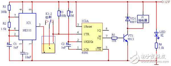
Its working principle is as follows:
First, an input signal is generated by the signal acquisition portion, and then processed by the signal processing portion, and the driving signals of other circuits are output, that is, signals for controlling the operation of other circuits; the motor control circuit portion receives the effective control signal output by the signal processing circuit. When the normal working drive motor rotates and draws water; the display decoding circuit drives the display to display the water level at the moment when receiving the valid signal outputted by the signal processing circuit; and the alarm circuit drives the alarm when receiving the valid signal output by the signal processing circuit Work to make it an alarm.
Handheld Megaphone,Portable Megaphone,Hand Held Loud Speaker,Portable Megaphone With Microphone
Shangqiu Huayitong electronic technology co., Ltd. , https://www.huayitongmegaphones.com