At the intersection, in order to avoid traffic jams and ensure traffic safety, it is stipulated that traffic vehicles must travel by road and not cross the road. Therefore, the corresponding sensing device must be used to monitor the violation behavior of the vehicle. At present, the recording processing of the red light behavior mostly relies on installing the corresponding sensing device under the waiting line. When a car passes, a specific signal is immediately issued, and the system performs judgment processing according to the signal, and then photographs the illegal vehicle through the intersection camera. recording. A similar method can also be used to detect the vehicle's crossing behavior, that is, using a sensing device buried in the ground. However, since the size and shape of the sensing device are limited by the width of the lane marking, in order to effectively detect the driving behavior of the vehicle, higher requirements are imposed on the measurement sensitivity. The current scheme generally uses a single-chip microcomputer to measure the frequency, and its sensitivity is low, and the anti-interference ability is poor. This is because the measurement frequency of the single-chip microcomputer counts the number of pulse signals within a certain time t, and reflects the frequency change according to the change of the number of pulses. Assume that the frequency of the sensing oscillator circuit is 100 kHz (this value is close to the practical application limit. If the oscillation frequency is increased, the energy will be emitted outward and electromagnetic interference will be generated around). If the statistical time is t=l ms, then Record 100 pulses, the maximum theoretical value of sensitivity can reach 1%, but in fact, the sensitivity can not be too high to remove the influence of unstable factors; if the statistical time is extended to 10 ms, the maximum theoretical value of sensitivity can reach 0. .1%, this not only affects the speed of reflection, but the actual value is also discounted, so the sensitivity still can not meet the practical application requirements.
Although there have been some improvements in the use of single-chip detection vehicles, it is difficult to fundamentally improve the detection sensitivity. To this end, a design scheme that uses the phase-locked loop technology to improve the sensitivity and anti-interference ability of the sensing device is proposed. Experiments show that the design can meet the practical application requirements.
2 phase-locked loop principle
   "Phase Lock" is the automatic control of phase synchronization. An automatic control closed-loop system capable of completing phase synchronization of two electrical signals is called a phase-locked loop. Phase-locked loops are widely used in technical fields such as broadcast communication, frequency synthesis, automatic control, and clock synchronization.
The phase-locked loop (PLL) is mainly composed of Phase Detector (PD), Voltage Controlled Oscillator (VCO), and Loop Filter (LF). composition. The PD is a phase comparison means for comparing the phases of the input signal Ui(t) with the output signal Uo(t) of the VCO to generate an error voltage Ue(t) corresponding to the two phase difference signals. LF is used to filter out high frequency components and noise in Ue(t) to ensure the required performance of the loop and increase the stability of the system. The voltage controlled oscillator is controlled by the control voltage Ud(t) for bringing the frequency of the LF closer to the frequency of the input signal until the frequency difference is eliminated and locked.
The working principle of the PLL is to compare the phase difference between Ui(t) and Uo(t), and generate Ue(t) to adjust the frequency of the VCO to achieve the same frequency as Ui(t). When the loop starts working, if the input signal frequency fi is different from the voltage controlled oscillator frequency fVCO, the natural frequency difference between fi and fVCO causes the phase difference to change all the time, resulting in the PD output error voltage UPD being within a certain range. Internal change. Under the control of the error voltage, the fVCO also changes. If fVCO can be equal to fi, it should be stable at this frequency when the stability condition is satisfied. After stabilization, fUi(t)-fUo(t)=0, the phase difference does not change with time, and Ue(t) is a fixed value. At this point the loop enters the locked state.
This article refers to the address: http://
3 System Design The existing technology is used to design the sensing circuit for initial detection of the vehicle. The detection circuit converts the output signal of the sensing circuit into an electrical signal that can be directly displayed or measured for further processing by the system. This part of the design is implemented using phase-locked loop technology.
3.1 Figure 1 shows a sensing circuit sine wave oscillator circuit. It is a three-point capacitor circuit, which is also a Cobbitz oscillator circuit. The sensing circuit is used to sense the presence of a metal object. In the design, the eddy current sensing method has been applied, and the buried detection coil is directly connected to the sinusoidal oscillation circuit, that is, the frequency of the output of the oscillation circuit is provided with a sensing signal.
In the circuit of Figure 1, Rbl=Rb2=62 kΩ; Rc=1 kΩ; Re=2.2 kΩ; Ce=Cb=10μF; C1=C2=0.1μF; L is the inductor coil, and the transistor VT1 is conjugate Amplify the configuration and work in an amplified state.
When the system is in a normal state, that is, when no car passes, the output signal us(t) of the sensing oscillation circuit is a sine wave whose frequency remains unchanged (f=f0). When a car passes, the frequency of us(t) becomes larger, that is, f=f', and the frequency difference is Δf=f'-f0, and the range is approximately several hundred hertz to several kilohertz. The oscillation frequency f of this circuit is:
It can be seen from equation (1) that f is related to the inductance L and the capacitance C1, C2 in the circuit (C1, C2 are fixed values), so f is a single-valued function of L. When L changes, the oscillation frequency of the oscillation circuit is also The opposite direction changes. The ground coil is connected as L to the circuit, and the change of the oscillation frequency of the circuit is detected to reflect the change of L, thereby realizing the detection of the metal object.
It is easy to know that f'>f0 is the output signal frequency when the vehicle passes by in the normal state, and the frequency of the output signal is f'. Since f' is not easy to calculate directly by the fixed formula, but can only be estimated by the experimental method, and the actual value does not need to know the specific value of f', it is only necessary to estimate the range of Δf=f'-f0.
3.2 Detection circuit
3.2.1 PLL circuit design Determines whether a vehicle has passed by detecting a phase-locked loop. When the vehicle moves to the coil buried in the ground, the output frequency of the sensing circuit changes, and the PLL loses lock. By detecting the lost lock signal, it can be known whether there is a car crossing. Because the detection circuit judges whether there is a vehicle passing by relative frequency change instead of absolute frequency change, it has self-adjusting ability and will not fail due to changes in the surrounding electromagnetic environment.
In this design, the PLL is used to track the frequency change of the output signal of the sensing circuit to generate the local oscillator signal u1(t). The specific requirements are:
(1) Within the frequency variation range (f0~fmax) of us(t), the PLL locks in other words, the center frequency of the PLL should be set between f0 and fmax, and the "capture range" of the PLL should be greater than or At least equal to the frequency variation range of us(t). This ensures that the PLL will always be locked when the frequency changes.
(2) The lock time established by the PLL cannot be too long or too short. If the lock time established is too short, the PLL is quickly locked and the difference frequency signal cannot be seen. If the lock time established is too long, it is difficult for the PLL to recover from the unlocked state to the locked state, making the reflection slower. Therefore, select the appropriate integral resistors R and C and choose the appropriate lock time.
The design is implemented with an integrated phase-locked loop CD4046. Figure 2 is its connection circuit. According to the working principle of CD4046, the center frequency is determined by C1 between pins 6, 7 and the grounding resistance R1 of pin 11, so select the appropriate R1, C1, so that the center frequency of the PLL meets the requirements. In order to increase the tunability of the PLL center frequency, a variable resistor R2 is connected in series with R1. Because the PLL here does not require a width of the input frequency, pin 12 is left floating.
Adjust the variable resistor R3 as shown in Figure 2 so that the voltage of pin 9 is U9 = Ucc/2 = 4.5 V. At this time, the output frequency of pin 4 is the center frequency of the PLL. Select C1=1 000 pF, R1=5.1 kΩ, R2=10 kΩ, then the center frequency f0=23.7 kHz, just meet the system requirements.
3.2.2 Determining the lock-up time According to the working principle of the phase-locked loop CD4046, the lock-up time is determined by the integral resistor capacitance between pin 13 (or pin 2) and pin 9. The output of pin 13 is charged and discharged by integrating capacitor C2, so that U9 changes, thereby adjusting the output of VCO, that is, the output frequency of pin 4.
4 Experiments and analysis of results In order to verify the feasibility of the design, a verification test was performed in the laboratory. Both the vehicle and the coil are scaled down in the same proportion. Using a normal diameter of 5 mm, the wire is wound around a 100 cm x 2 cm coil (number of turns n = 16) for simulating the ground coil of the actual application; and a 20 cm x 10 cm rectangular metal plate is used to simulate the actual vehicle. The experiment proves that the output frequency f0=23.7 kHz under normal conditions, the maximum output frequency when the vehicle passes (the value measured when the metal plate is completely placed on the coil) is fmax=24.5 kHz, so â–³fmax =0.8 kHz.
Change the vertical distance of the metal plate to the coil and measure the output frequency of the PLL after the metal plate moves over the coil. The experimental results show that the closer the metal plate is to the coil, the larger the output frequency of the PLL. Using an oscilloscope to observe the state of the PLL from loss of lock to lock, it was found that a significant change from loss of lock to lock can be observed when the metal plate is 2 to 15 cm away from the coil. When the metal plate is stationary on the coil for a long time, the PLL can also be restored to the locked state. The vertical distance from the metal plate to the coil corresponds to the distance from the chassis of the vehicle to the underground coil in practical use. According to the corresponding proportion, the range that can be measured by the experiment can fully meet the practical needs. Because the experiment is to observe the oscilloscope to determine that the PLL is out of lock, for the obvious effect, the set lock time is longer. In practice, other methods can be used to detect the loss of the PLL to determine that there is a vehicle passing through, and the corresponding circuit parameters can be adjusted to make the locking time shorter and the detection sensitivity increased accordingly. Experiments show that the detection sensitivity achieved by PLL completely meets the system requirements.
5 Conclusion The vehicle detection technology realized by phase-locked loop technology is more reliable than the current vehicle detection technology using single-chip counting. Moreover, by detecting the loss of lock of the phase-locked loop, it is determined whether there is traffic passing, which is relative frequency change instead of absolute. The frequency change is judged, so it has self-adjusting ability and will not fail due to the center frequency offset caused by the change of the surrounding electromagnetic environment. Therefore, the phase-locked loop technology proposed in this paper has obvious effects in improving sensitivity, and has low cost and wide application prospects.
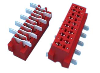
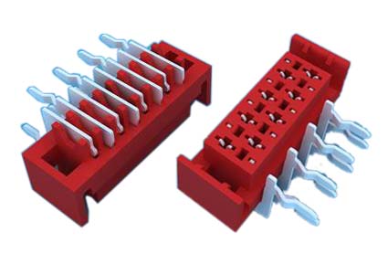
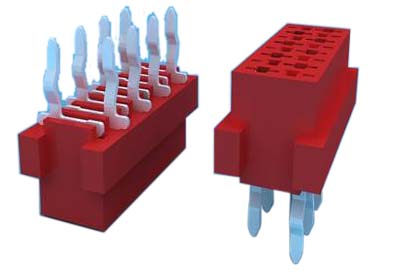
1.ANTENK Insulation Displacement termination connectors are designed to quickly and effectively terminate flat cable in a wide variety of applications. The IDC termination style has migrated and been implemented into a wide range of connector styles because of its reliability and ease of use. Click on the appropriate sub section below depending on connector or application of choice.


SPECIFICATION
Current Rating: 1.0Amp
Insulation Resistance: 1000MΩ min
Contact Resistance: 20mΩ max
Withstand Voltage: 500V AC/DC
Operating Temperature: -40°C to +105°C
Contact Material: Phosphor Bronze
Contact Plating: Au Over Ni
Insulator Material: High Temperature plastic UL94V-0
Ribbon Cable Connectors,Cable Connector,Cable Assembly,Connector Flat Ribbon Cable
SHENZHEN ANTENK ELECTRONICS CO,LTD , http://www.antenk.com