At present, passenger car overload operation is the primary problem to be solved in traffic control. This design can be applied to the inspection of passenger car overload through administrative intervention and other means, which facilitates the work of the traffic police [1].
This article refers to the address: http://
The system design realizes the inspection and control of the overload of the passenger car through the combination circuit of the single chip and the sensor. The detection system can automatically check the number of passengers in the vehicle and display them. When the inside of the vehicle is overloaded, a voice prompt is issued, and the vehicle starting device is automatically turned off to make it unable to operate, thereby ensuring driving safety.
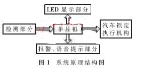
1 system composition
The block diagram of the system is shown in Figure 1.
2 System principle analysis
This design makes full use of the features of the PIC16F877 microcontroller, such as easy programming and driving ability [2], through the query command to generate interrupts to achieve system display, voice alarm and car engine lock and other functions.
2.1 Sensor detection and signal amplification filter design
The design of this part adopts two reflective photoelectric eyes, which are installed at the appropriate position of the door of the passenger car. According to the different timings of the infrared light emitted by the two electronic eyes when the passenger passes through the door, the single-chip microcomputer determines whether the passenger is getting on or off. The overall circuit diagram of the hardware circuit design of this part is shown in Figure 2.
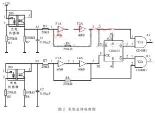
In the circuit of Figure 2, F1A~F4A are amplified filter sections composed of CMOS integrated six-inverting amplifier CD4069; ICA is a CMOS dual D flip-flop composed of CD4013, Y1A, Y2A are CD4081 four 2-input and gate These two parts are logically operated with the two-way sensor detection signals of the 4069 output, and finally output appropriate level signals at the output terminals of Y1A and Y2A, respectively, which are sent to the T0CKI pin and the T1CKI pin of the PIC microcontroller (ie, counter 0 and counter 1). Clock input).
There must be a certain distance between the installation positions of the two sensors (between 30cm and 50cm). When no one passes the sensor (the sensor is indicated by E1 and E2 below), the infrared light emitted by the infrared diode is not irradiated onto the phototransistor. The signal sent to the microcontroller is always a constant low level and the system does not count. When someone gets in the car, first block E1, then the light from the infrared diode of E1 is irradiated on the person and reflected on the light-receiving transistor. The A1 point in the circuit generates a high-level signal, which is amplified and filtered, and finally logically operated. A3 outputs a low level signal. Then the human body completely blocks E1 and E2, then leaves E1 to block E2 and finally leaves. Therefore, the level of the A3 point is high and low during the entire boarding process, that is, a boarding pulse signal is sent to the STATUS register of the PIC microcontroller for counting, and the output state of the B3 point is unchanged. . The specific detection method and pulse generation timing are shown in Fig. 3.
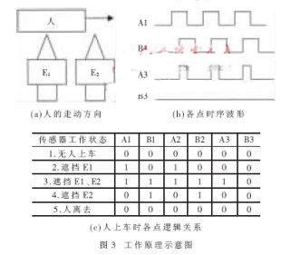
When the person gets off the vehicle, the occlusion sequence is reversed. The pulse timing generated by the B3 point is reversed. The signal is sent to the STATUS register of the PIC microcontroller to count down. The microcontroller can calculate the actual number of people in the cabin by program simulation. Stored in registers.
2.2 Display part of the design
Because the I/O port drive capability of the PIC16F877 MCU is strong, the circuit of the display part uses the PIC16F877 MCU to directly drive the two common anode LED digital tubes [3].
The RC6 and RC7 ports respectively control the power supply of the tens and single digits of the digital tube. When the corresponding port becomes low level, the corresponding triode will be turned on, and +5V will supply the corresponding bit of the digital tube through the IN4148 diode and the driving transistor. At this time, as long as the RB7 port sends out the digital display code, the digital tube can display the number normally.
2.3 Design of the voice alarm part
This part mainly adopts the ISD4004 voice chip of Winbond's 10-minute specification. It is directly driven by the RC3 and RC5 ports of the PIC16F877 SPI module. The circuit is simple, not afraid of power loss, clear pronunciation, large storage capacity, convenient programming, and can be adapted to passenger cars. surroundings.
Since the ISD uses a 3V power supply, and the PIC uses a 5V power supply, in the circuit design, when the I/O port of the MCU is output, the method of first connecting the 10kΩ resistor to the ISD SPI port is adopted; and the MIS0 The port is input by ISD output and PIC16F877. In order to make the PIC16F877 accurately recognize its level, an inverter connected to the NPN transistor is added to the MIS0 pin to provide sufficient voltage to the PIC4 pin of the PIC0F877. Therefore, all the read signals of MIS0 should be reversed in the program.
In order to facilitate voice input, a microphone is added to the 17th pin of the ISD4004. Since the sampling frequency of the voice chip itself is high, it is not necessary to connect the AGC circuit, and a clear voice can be recorded.
After the voice output of the ISD4004 is capacitively coupled, it is connected to the audio power amplifier chip TDA2822 and amplified by the speaker.
2.4 Circuit design of the engine lock part
Because the passenger car engine is a gasoline engine, the combustion mode of the gasoline engine is ignited by the spark plug, and the flashover of the spark plug is caused by the signal generator installed in the distributor, and the ignition module is connected according to the signal of the received signal generator. By switching off and switching off the primary circuit of the ignition system, the secondary circuit of the ignition system senses a change in the voltage of the primary circuit to produce a high voltage ignition. Therefore, as long as the gasoline engine performs a circuit to cut off the low voltage circuit of the ignition circuit, the high voltage circuit does not induce an electric spark to ignite the mixed gas.
In this design, according to the signal detected by the PIC16F877 MCU, whether it is overloaded, a high or low level signal is output at the I/O port, and the solenoid valve is opened and closed to amplify the low voltage circuit of the ignition circuit.
3 software design
3.1 counting function program implementation
The main function of this part of the program is to send the two-way get-off signal detected by the sensor to the STATUS register of the PIC microcontroller for counting up and down, and to cycle the real-time data and the upper limit number (such as 50 people) preset in the W register. The query comparison is performed intermittently, and once equal to 50, an interrupt control voice chip is generated for voice alarm, and when it is greater than 50, an engine lock circuit is executed.
3.2 Program realization of LED display part
The main function of this part of the program is to query and check the display control bit of the single-chip microcomputer, so that the high and low positions of the digital tube can be refreshed continuously, and the purpose of displaying the number of passengers on the bus in real time is achieved.
3.3 Software Control Program Design for Voice Part
The main function of this part of the program is to continuously query the SPI chip selection bit RA5 and the voice control bit RC5 of the PIC16F877. Once there is an interrupt signal, the SPI module of the MCU reads the corresponding pre-recorded voice program from the memory of the voice chip. .
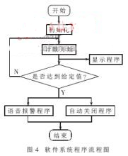
3.4 Software Control Program Design Flow Chart
The system software control program design flow chart is shown as in Fig. 4.
The intelligent random detection bus overload system studied in this paper uses photoelectric sensor and PIC single chip to form an overload detection and processing structure, and drives the electromagnetic valve to control the ignition circuit of the engine to achieve overload control. Modern transportation systems have complex sensor networks. Sensors are the "eyes" and "ears" of electronic control systems [6]. They tell computer systems to detect traffic information such as speed, weight, and real-time traffic conditions, greatly improving traffic management. effectiveness. On the other hand, the sensor device configured by the car itself feeds the relevant parameters of the running state of the car to the computer control system at the speed of light, so that the system makes reasonable adjustments. These together constitute an intelligent transportation system and the development direction of the future transportation system.
Lithium Polymer Battery Power Bank is Build-in intelligent recognition voltage imported chip,is speed Power Bank and slim power bank. Lithium Polymer Battery Power Bank can automatically identify the mobile phone, tablets, and other digital products charge. Lithium Polymer Battery Power Bank is used Precise electronic board, and it have prevent overcharge,discharge, discharge and prevent leakage, short circuit and high temperature resistant.High quality high capacity batteries, durable. Lithium Polymer Battery Power Bank Support for fast charging, no memory effect, charging circuit number up to 1000 times. Lithium Polymer Battery Power Bank is very super slim(ultra thin, lightweight) . it have Standard USB output and Micro USB input so that simple and easy to carry it in our daily life.
New Products Cellphone Super Slim Power Bank 4000mah

Capacity: 4000mAh
Input: 5V-1000Ah
Output 1: 5V-1000Ah
Compatibility: All phones
Size: 115X65X10.2mm
Color: Black,Silver,Blue,Golden,Purple
Support for fast charging, no memory effect, charging circuit number up to 1000 times.
Standard USB output, Micro USB input, simple and easy to carry.
Ultra Slim Portable 4000mah Mobile Charger Power Bank

Material: metal case
Weight: 120 g
Size: 116 (L) * 65 (W) * 7.5 (H) mm
Input: 5V-1A
Output: 5V-1A
Capacity: 4000mah
Interface: Micro USB
It is lightweight, portable, environmental friendly and economic efficiency.
It has high efficiency of power conversion and electricity-saving function.
Cheapest Price Wholesale Shenzhen Portable Power Bank

Size: 96*62*6.6mm
Color: White
Weight: 70g
It is small and protable, easy to carry.
Luxury plastic outer skin, delicate and cabinet.
Exquisite workmanship, high-capacity.
Metal Case Ultra Thin 3000mah Power Bank For Mobile Phone

Weight: 130 g
Size: 100 (L) * 60 (W) * 10 (H) mm
Input: 5V-1A
Output: 5V-1A
Repeatedly use of a single charge, portable design, convenient to carry.
Mobile power storage, portable for both indoors and outdoors.
Manufacturer Wholesale New Power Bank for Promotional Gifts

Weight: 170 g
Color: Silver, Gold, Blue, Black, Green
Size: 117mm * 65mm * 10mm
Input: 5V-1A
Output: 5V-1A
Capacity: 5000mah
Electricity-saving function.
Environmental friendly and economic efficiency.
These Lithium Polymer Battery Power Bank are compatible with:
Digital devices like mobiles , For iPhone 4s, For HTC Amaze, For Nokia, For Samsung galaxy S2, S3, Note, note2, For Nexus, For Samsung Gem, and other devices that uses Micro USB, Mini USB, For Apple 30 Pin and 2.0mm adapter.
Lithium Polymer Battery Power Bank
Lithium Polymer Power Bank,Power Bank Li-Ion Polymer,Li-Po Power Bank,3000Mah Lithium Battery Power Bank
Reteck Storage Device Co., Ltd. , http://www.reteck.com