1 Overview
In recent years, the rapid development of LED lighting technology, LED light efficiency, color temperature, color and other light color indicators have attracted much attention at the same time, LED thermal characteristics and life expectancy has also been more and more people's attention, especially thermal characteristics, It has a significant effect on the performance and lifetime of LED light color. However, the detection of thermal properties and lifetime is challenging.
The thermal characteristics of LED mainly include LED junction temperature, thermal resistance, transient change curve (heating curve, cooling curve) and so on. The junction temperature refers to the temperature of the PN junction of the LED. The thermal resistance refers to the ratio of the temperature difference between the LED cooling channel and the dissipated power on the channel. It is used to characterize the heat dissipation capability of the LED. Studies have shown that the lower the thermal resistance of the LED is. The better the heat dissipation performance, the corresponding LED light efficiency is generally higher and the longer the life. The key to the detection of thermal characteristics lies in the accurate measurement of the LED junction temperature. There are generally two methods for testing the LED junction temperature. One is to measure the temperature of the surface of the LED chip by infrared temperature measurement and regard it as an LED. Junction temperature, but the accuracy is not enough; the other is through the temperature-sensitive parameter (temperature-sensitive parameter, abbreviated as TSP) to obtain PN junction temperature, which is currently the more common LED junction temperature test method, the technical difficulty lies in the test equipment High demand.
The lifespan of an LED is mainly reflected in its light decay. Usually, the light output of the LED is attenuated to 70% or 50% of the initial light output as an indicator for judging the lifetime failure, that is, the luminous flux maintains the lifespan. However, since the LED is a high-reliability device, the lifetime will generally exceed several thousand hours or even more than 10,000 hours. It is very difficult to directly measure the wait for light attenuation to a specified value in industrial applications.
2, LED thermal characteristics test
2.1 LED junction temperature and thermal resistance measurement US EIA/JESD51 "Methodology for the Thermal Measurement of Component Packages" series of standards and national standards SJ20788-2000 "semiconductor diode thermal impedance testing method", GB/T4023-1997 "semiconductor device discrete devices and Integrated current Part 2: Rectifier Diodes, QB/T 4057-2010 "Electrical Devices for Performance Requirements for Light Emitting Diodes" and other international and domestic standards have introduced in detail the method of measuring the junction temperature and thermal resistance through the temperature sensitive parameter TSP. For LEDs, TSP is the forward voltage across the PN junction. In determining the current, the forward bias of the LED and the junction temperature are approximately inversely proportional to each other. The resulting change in junction temperature is:
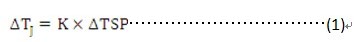
In formula (1), K is the temperature sensitive coefficient, which can be obtained from the following formula:
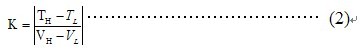
In equation (2), VL is the forward voltage of the LED under the measuring current IM (small current) when the low junction temperature TL (eg, 25°C), and the LED is measuring the current when VH is the high junction temperature TH (eg, 100°C) IM The forward voltage under.
The LED junction temperature measurement timing is shown in Figure 1:
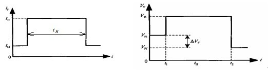
Figure 1 (a) the current timing diagram (b) voltage timing diagram 1) first applied to the LED forward test current IM, measuring the forward junction voltage VFI;
2) Use the heating current IH instead of IM to add the two ends of the LED to be tested, heat for a certain time (tH) until the LED reaches a stable state, and measure the heat dissipation power (PH) on the measured LED cooling channel;
3) Reuse IM immediately replace IH added to both ends of the LED to be measured, and measured the positive junction voltage drop (VFF);
4) Calculate the junction temperature and thermal resistance of the LED:
According to the above principle, the junction temperature calculation formula is:

The thermal resistance formula is:
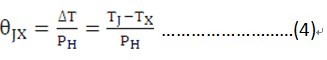
In equation (3), the initial temperature, in equation (4), is the temperature at a specified point on the heat dissipation path, for example, the ambient temperature or the housing temperature. For LEDs, part of the input electrical power is used for the LED to emit light and the other part generates heat, and the heat dissipation power PH is often difficult to distinguish from the total input electrical power. Therefore, to facilitate and simplify the measurement, QB/T 4057-2010 proposes " The concept of thermal resistance refers to the use of input total power to replace the heat dissipation power in (4). "Reference thermal resistance" has been used more and more because of its convenient measurement and good reproducibility.
Under the action of the heating current IH, monitoring the rise of the junction temperature of the LED and obtaining the heating curve is also very meaningful. Figure 2 shows a typical heating curve. It can not only determine whether the LED has reached thermal equilibrium, but also the structure and heat dissipation capacity of the LED. Analysis has a reference role.
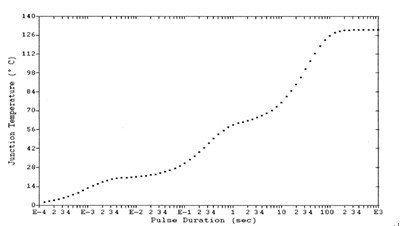
The technical difficulty of obtaining the heating curve in the heating curve of Fig. 2 is that the test current and heating current switching time must be short enough, and the collection of transient data must be very rapid. Switching time and data acquisition time generally reach several to ten microseconds, otherwise it can not reflect the actual change process of LED junction temperature, resulting in the final test of the thermal resistance is greatly underestimated.
2.2 Measurement of LED light color parameters with temperature curve The light color parameters of packaged LEDs are generally given at 25±1°C for PN junctions. In practice, the junction temperature is usually higher than 25°C. Large changes in color performance can occur, which also confuses the application of packaged LEDs. Therefore, it is necessary to monitor the LED light color parameters with the junction temperature changes, as shown in Figure 3. The measurement of the light color parameter with the temperature change curve of the PN junction is similar to the measurement method of the K coefficient.
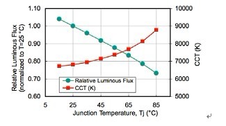
Figure 3 The relationship between the luminous flux and color temperature of a white LED as a function of junction temperature [1]
The influence of the ambient temperature (reference point temperature) on the light color parameters of the LED is more intuitive, and it is more instructive to the application of the LED. This measurement can be performed in the following accelerated training and life test chambers.
3, LED life test
3.1 Accelerated Experience and Life Test of LEDs Unlike traditional lighting products, the end of life of LED products is mainly reflected in light attenuation to a certain extent, such as attenuation to 50% or 70% lumen maintenance, ie L50 or L70. In addition to the requirements of the existing international standards or national standards for life time, it is generally required that the luminous flux maintenance rate should not be lower than 92% when the flash point is 3000 hours, and the luminous flux maintenance rate should not be lower than 88% when the flash point is 6000 hours; The standard classifies the LEDs according to their lumen maintenance at 6000 hours. The US standard LM-80-08 is designed for measuring the lumen maintenance lifetime of packaged LEDs and LED modules. It proposes to measure the lumen maintenance of LEDs at three enclosure temperatures: 85oC, 55oC, and the temperature selected by the manufacturer. The sophisticated LED at high temperature is mainly used to simulate the actual working environment of the LED under test. Experienced test time is 6000 hours, and extrapolation calculations can be used to obtain the life time of the LED. Figure 4 shows the life projection curve:
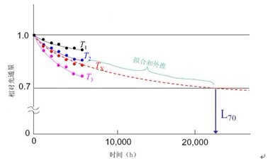
Figure 4 LM-80 Life-Depth Curve LED has a long lifetime, and the life-time test under rated conditions is extremely time consuming. In addition to the extrapolation of the life time of L50 or L70 introduced according to the change of the initial lumen maintenance rate, a solution for accelerating the aging life test can also be used. That is, under the premise of not changing the LED failure mechanism, the stress condition is increased. To speed up the decay of the LED, thus reducing the life test time [2-3]. Accelerated life test can be divided into two accelerating methods, increasing the test current and increasing the ambient temperature. The current accelerated test is the main method. Accelerated life expectancy values ​​can be calculated based on the Arrhenius model for LED life expectancy under rated conditions.
4, detection equipment overview
4.1 thermal characteristics of the detection equipment and thermal photoelectric comprehensive test system According to the thermal characteristic detection method discussed in section 2.1 above, its technical difficulty is that the test equipment performance requirements are very high: current switching and sampling rate must be fast enough, voltage measurement accuracy and high The external temperature of the LED must be steadily controlled. The international T3Ster LED thermal resistance test system in Hungary and the United States Phase11 thermal resistance analyzer can basically meet the requirements, but these two instruments are expensive, and bring economic obstacles to industrial inspection. Based on the in-depth study of the relevant standards, the Chinese company has developed a HEO-200 thermoelectric test system that meets the above technical requirements according to the characteristics of the LEDs, and the price is significantly lower than that of foreign equipment.
The HEO-200 uses MOS (Metal Oxide Semiconductor) technology to achieve current switching. The switching time is less than 10μs, which can effectively avoid the test error caused by junction temperature cooling. In the collection of transient data, a cyclic test method is used, that is, in step 2) described in section 2.1, transient data is acquired by rapidly disconnecting the heating current in a very short time to obtain the transient data. The sampling rate of 1MHz/s, the accuracy of the acquisition of transient data up to 1μs, to ensure the accuracy of the analysis results.
The system's physical objects are shown in Figure 5, including the test host, static air test box, and professional measurement and analysis software. In order to ensure the accuracy of the measurement results, the system uses a built-in constant current source to provide voltage to the LED to ensure that the LED Luminous stability. The system can realize accurate measurement of junction temperature, thermal resistance (transient thermal resistance, steady state thermal resistance), heating curve and cooling curve.
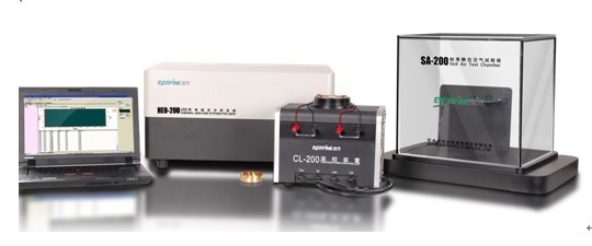
Figure 5 LED thermal characteristics detection device to achieve the measurement of the LED light color parameters with the junction temperature curve and thermal resistance measurement without light power, based on the above system, the configuration of a high-precision fast spectrometer with sync trigger function and the integrating sphere Realize the measurement of light color parameters.
4.2 Accelerated training and life testing system For the accelerated training and life testing, no matter what kind of life prediction model or what kind of life grade classification method is adopted, the hardware measurement device is basically the same, generally including the constant temperature test box, the sophisticated test host, and multiple paths. Temperature inspection instrument, photometer and professional measurement and control software. In the test process, the constant temperature test chamber can control the ambient temperature of the LED to reach the specified temperature value. The sophisticated test host is used to power the LED under test and complete the measurement of various LED electrical parameters. A multi-channel temperature inspection instrument is used to measure each LED. The temperature, photometer used to measure the photometric parameters of the LED, the three above will feedback the results of the test to the system software, software analysis to calculate the life of the LED to be measured. The physical device is shown in Figure 6.
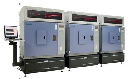
Figure 6 Accelerated Experience and Life Detection System
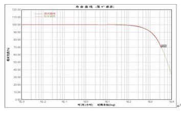
Figure 7 shows the typical LED lifetime curve.
According to the above measuring device, under the conditions of different incubators, the luminosity of the LED to be measured is measured, and the LED luminosity-ambient temperature-time curve (temperature characteristic test) can be obtained. If the spectrometer device is configured, it can be obtained. Test LED color - ambient temperature - time curve (temperature characteristics test). Figure 8 shows the typical LED relative luminous flux as a function of ambient temperature.
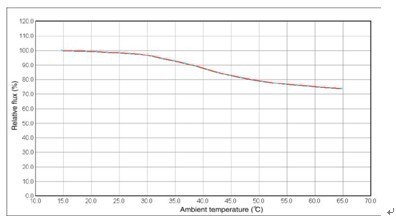
Figure 8 LED luminous flux changes with the ambient temperature curve 5, summary
Due to the difficulty of direct measurement, the evaluation of the thermal properties and lifetime of LEDs is challenging. However, accurate detection of these two major performances is indeed an important basis for evaluating current LED levels. Our country has made more in-depth research on these two important performance tests, and independently developed related test equipment, which can meet the requirements of the current domestic and foreign standards, enabling Chinese industry to carry out high-precision, low-cost thermal characteristics And life performance testing.
A weak electrical cable is a cable used for security communications, electrical equipment, and related weak electrical transmissions.
Wire and cable refers to materials used in power, communications, and related transmission applications. There are no strict boundaries between "wires" and "cables." Generally, a product with a small number of cores, a small product diameter, and a simple structure is called a wire, a non-insulated wire is called a bare wire, and the other is called a cable; a conductor having a large cross-sectional area (greater than 6 square millimeters) is called a large wire. Small (less than or equal to 6 square millimeters) is called a small wire, and insulated wire is also called a wire.
Wire and cable mainly includes bare wires, electromagnetic wires and insulated wires for electrical appliances, power cables, communication cables and optical cables.
composition
It consists of an inner conductor, an insulation, an outer conductor and a sheath from the inside out;
Inner conductor: Since the attenuation is mainly caused by the resistance of the inner conductor, the inner conductor has a great influence on the signal transmission.
Insulation: affects attenuation, resistance, return loss and other properties
Outer conductor: return conductor, shielding
Civil Building Cable,Suspension Cable,Pvc Insulated Wire,Control Power Cable
Jiangsu QiSheng Cable Co., Ltd. , https://www.shuaihe-cable.com