1 Introduction
The brushless DC motor (BLDC) replaces the brush and the commutator with an electric control device, which improves the reliability of the motor, and has the advantages of small size, high efficiency, low noise, etc., and is widely used in consumer and industrial applications. In BLDC control, the excitation must be synchronized with the rotor position, so one or more rotor position sensors are often used to determine the position of the motor rotor relative to the motor stator. The BLDC control scheme using the position sensor is relatively simple. The range of the rotor is determined according to the output of the position sensor, and the motor windings are commutated accordingly. However, the use of position sensors introduces disadvantages such as increased system cost and reduced reliability, and in some special cases, such as when the motor is in an immersed environment, the sensor cannot be installed. This requires the motor to operate without a position sensor.
2. Sensorless control scheme
Figure 1 shows the BLDC commutation diagram with Hall sensor. The scheme uses a conventional 120° energization mode (six-step commutation). In order for the motor to operate, the energized phase must be switched at regular intervals (ie, commutation). For regular energization, six equidistant commutations are required for each electrical cycle. Each step or interval is equivalent to 60 electrical angles. The six intervals make up 360 electrical angles or one electrical rotation. Two windings are energized in each section and one winding is not energized. To properly commutate the motor, the absolute position in the electrical cycle must be measured. Three Hall sensors are used to provide the positional information required for six commutations.
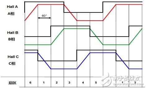
Figure 1 BLDC commutation diagram
In a sensorless control scheme, the rotor position must be obtained in other ways. The acquisition of rotor position is a key technology in BLDC position sensorless control. Common rotor position detection includes back electromotive force zero-crossing detection method, back electromotive force third harmonic integral detection method, freewheeling diode detection method, and flux linkage estimation method. The most commonly used and most classic is the counter-electromotive zero-crossing detection method. The back-EMF zero-crossing detection method does not require detailed knowledge of the motor characteristics and can be applied to a variety of motors.
In the six-step commutation process, two windings are energized in each interval, and one winding is not energized. In this way, the current on a certain phase will be zero on the unpowered winding, and the voltage can still be seen on the motor lead. This voltage is the counter electromotive force. Simply put, the back electromotive force (EMF) is the voltage generated by the stator windings when the permanent magnet motor rotor rotates. The magnitude of the back EMF is proportional to the motor speed. In Fig. 1, the phase C voltage in the first sector and the phase B voltage in the second sector are the counter electromotive forces generated by the stator windings.
Assuming that the motor is driven by a ±UV voltage, the back EMF signal is symmetric about 0V. If the back EMF signal is a straight line, the signal will pass through the zero line at half of the interval (that is, at the 30° electrical angle of the interval). This point is called the zero crossing. After the zero-crossing event, the next commutation is performed after a 30° electrical angle. Therefore, the position of the rotor can be estimated accurately when the zero crossing is detected, so that the motor windings are commutated at the correct time. as shown in picture 2.
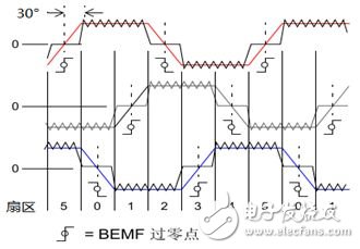
Figure 2 BEMF zero crossing and commutation diagram
3. Zero crossing detection scheme
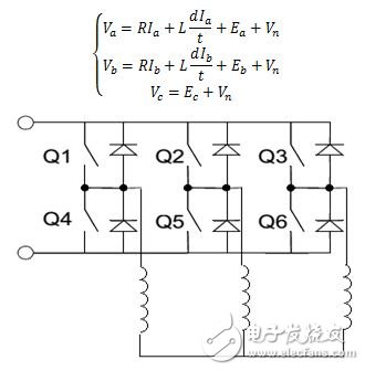
Figure 3 BLDC drive circuit topology
Figure 3 is a typical three-phase BLDC drive circuit topology. Assume that the three-phase terminal voltage is Va, Vb, Vc; Vn is the neutral point voltage; Ea, Eb, Ec are three opposite electromotive forces; Ia, Ib, Ic are three-phase current, R is phase resistance, and L is inductance. When the phase C is a non-conducting phase, Va+Vb+Vc=0 and the above equation can be obtained according to the zero crossing point:
3Ec=2Vc-(Va+Vb)
According to the above equation, there are three different zero crossing detection methods:
1. Sampling the three-way voltage directly with the ADC and judging the zero-crossing point according to the above formula. This algorithm needs to sample multiple ADC voltages, and requires software filtering algorithms, which have certain requirements for ADC and MIPS.
2. Sampling the non-energized phase voltage when the PWM output signal is OFF and comparing it to zero voltage. This algorithm is advantageous at low speeds because the back EMF signal is weak at low speeds. The sampling area of ​​this algorithm is just the non-energized phase terminal voltage zero-crossing area. However, when the duty cycle of the PWM is relatively high, the sampling failure is likely to occur because the time available for sampling is too short.
3. When the PWM output signal is ON, sample the non-energized phase voltage and compare it to half of the bus voltage. This algorithm has a wide range of speed regulation and is more versatile.
This scheme uses the third algorithm to perform zero-crossing detection.
4. Design based on PSoC 4
Introduction to PSoC 4
PSoC 4 is a family of programmable embedded system controllers based on the ARM Cortex-M0 CPU, which combines programmable analog resources, programmable interconnects, user-programmable digital logic, general purpose fixed-function design, and high-performance ARM Cortex -M0 CPU subsystem. Compared to all aspects of the PSoC3 and PSoC5 series, PSoC 4 has been greatly improved. PSoC 4 now includes two product families, CY8C4100 and CYCY8C4200. The PSoC4100 series is the lowest cost PSoC based on the ARM core, bringing PSoC flexibility and high integration into cost-sensitive, high-volume production. The PSoC4200 family features a faster processor, higher ADC sampling speed, and an enhanced Universal Digital Block (UDB) based on PLD. The main features are summarized below.
â— High performance Cortex-M0 CPU core. Based on the 48 MHz ARM Cortex-M0 central processor, single cycle multiplication is supported.
â— Fixed functions and configurable digital modules. Includes four independent centrally aligned PWMs that support complementary programmable deadband and synchronous ADC operation; two serial communication modules (SCBs) that operate as SPI/UART/I2C serial communication interfaces;
â— High performance analog system. Includes a 12-bit 1 Msps ADC that supports zero-overhead channel switching; two op amps that support comparator mode and SAR ADC input buffering; two low-power comparators; and a capacitive sensing (CapSense) module for excellent performance Signal to noise ratio and waterproof function; two current digital-to-analog converters (IDAC).
â— Highly programmable digital logic. Four programmable digital logic blocks (UDBs), each containing two tiny programmable logic arrays and one 8-bit data arithmetic unit.
â— Flexible and programmable internal interconnection.
Sensorless BLDC control scheme based on PSoC4
PSoC4 integrates four independent TCPWM modules that support center-aligned, complementary programmable deadband and synchronous ADC operation; two op amps that support comparator mode and SAR ADC input buffering; programmable synchronous logic Digital Logic Module (UDB); an analog multiplexer that can switch analog channels freely; rich on-chip resources integrate the chips required by the master circuit into one chip for high integration. Figure 4 shows the PSoC4 sensorless BLDC hardware control block diagram.
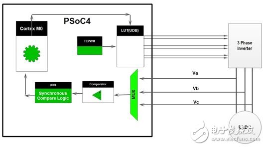
Figure 4 PSoC4 sensorless BLDC hardware control block diagram
Compared to other solutions, the PSoC4-based sensorless BLDC solution has the following advantages:
1) Adopt a cost-effective Cortex-M0 core. The Cortex-M0 is the smallest and most energy-efficient ARM processor available on the market. It has a small code footprint and can achieve 32-bit processor performance at an 8-bit processor price, which can significantly save system cost.
2) Internally integrated two support comparator mode and programmable digital logic module (UDB), with internal analog multiplexer can eliminate zero-point detection by hardware without external chip, reducing system cost.
3) Internally integrate two low-power comparators for hardware protection or error signal processing. Most of the common solutions in the market use an external comparator to do this. Using PSoC4 can further reduce BOM and reduce costs.
4) The LUT table hardware realized by UDB realizes commutation logic, which is faster and more reliable than software.
5) Reduce PCB space and BOM cost. Because PSoC4 integrates most of the peripherals and other rich modules required for motor control, it enables a highly integrated design.
6) Flexible communication interface. PSoC's special programmable architecture provides an extremely flexible communication interface to meet the needs of a wide range of applications.
Design example based on PSoC4
1) Schematic design
According to the control block diagram of Figure 4, we have designed the BLDC control schematic shown in Figures 5 and 6.
The three-phase terminal voltage is connected to the internal analog multiplexer via IO. The analog multiplexer dynamically switches the non-energized phase to be sampled according to the commutation state and is connected to the on-chip comparator. The on-chip comparator is compared to half of the bus voltage and the output signal is connected to the input of the D flip-flop. The clock signal of the D flip-flop comes from the output of the PWM module in the digital block. In this way, a comparison result of the terminal voltage and the half bus voltage at which the PWM is at a high level can be obtained by the D flip-flop. The flipping moment of the comparator is the zero-crossing of the back EMF. When the output of the comparator is inverted, an interrupt can be triggered to notify the CPU to perform the corresponding processing. At the same time, the on-chip comparator also has the function of hysteresis comparison. That is, the comparator output is not exactly the same as the voltage flipped from top to bottom, but has a hysteresis voltage of about 10 mV. This feature prevents the comparator output from being triggered by glitch.
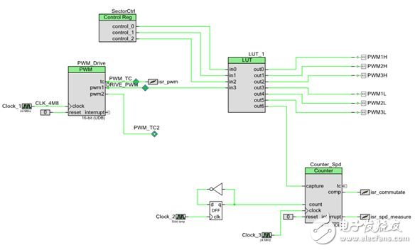
Figure 5 Schematic diagram of zero crossing detection
In the zero-crossing interrupt, the CPU can directly drive the three-phase full-bridge circuit by directly controlling the UDB commutation logic table LUT through the control register to complete the hardware commutation of the motor. At the same time, the commutation signal is also synchronously input to the timer to complete the motor speed detection.
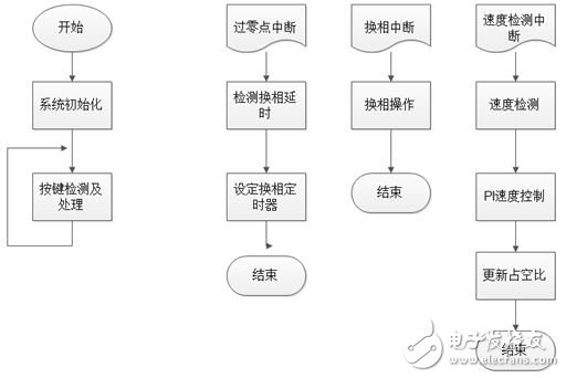
Figure 6 Schematic diagram of PWM and commutation logic
2) Programming
The main program first initializes and configures the internal resources of PSoC4, first detects the start and stop commands of the button in the main loop, and performs corresponding operations. According to FIG. 5 and FIG. 6, the program mainly has three interrupts: a zero-crossing detection interrupt, a commutation interrupt, and a speed detection interrupt. In the zero-crossing detection interrupt, the program mainly completes the calculation of the commutation delay and the setting of the commutation timer; the commutation interrupt mainly completes the operation of the LUT control register to complete the commutation logic; the speed detection interrupt mainly completes the PI detection of the speed detector . The relevant flow chart is shown in Figure 7.

Figure 7 program flow chart
Experimental result
Compile the project in PSoC Creator environment, and connect PSoC4 development board, three-phase full-bridge driver board and BLDC motor. After power-on, the motor can run normally. Figure 8 shows the three opposite electromotive force waveforms when the motor is running. It can be seen that the BLDC runs smoothly and the back electromotive force is a standard trapezoidal wave.
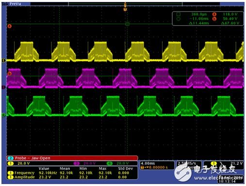
Figure 8 Three opposite electromotive force map
5. Summary
The above example shows how to implement a sensorless BLDC control scheme on Cypress's next-generation programmable system-on-chip PSoC 4 platform. PSoC 4's unique analog multiplexer, programmable digital logic module and internal comparator module enable flexible hardware zero-crossing detection schemes. At the same time, PSoC 4's internally integrated programmable UDB can embed the commutation logic in the form of PLD in the chip to achieve fast and reliable hardware commutation. PSoC 4 is the latest addition to Cypress and features a unique optimization for motor control. With its rich resources and high flexibility, users can easily design highly integrated, low-cost, and superior motor control solutions.
Exterior Elevator,Outdoor Escalator,Escalator Outdoor,Outdoor Escalator Weatherproof Escalator
XI'AN TYPICAL ELEVATOR CO., LTD , https://www.chinaxiantypical.com