The sixth chapter is to reuse the peripheral driver code . This article contains the first four sections of the 6.3 RTC real-time clock:
6.3.1 PCF85063
6.3.2 RTC Universal Interface
6.3.3 Alarm Clock Common Interface
6.3.4 System time
6.3.5 Special function control interface
6.3 RTC Real Time Clock
In this section, PCF85063 is taken as an example to introduce the RTC universal interface and the alarm universal interface. In the last two sections of this section, two other RTC chips will be introduced: the RX8025T and the DS1302. Although they differ from the PCF85063, they can be operated using the same common interface, enabling cross-platform multiplexing of RTC applications.
> > > 6.3.1 PCF85063
1. Device introduction
The PCF85063 is a low-power real-time clock/calendar chip that provides real-time time setup and acquisition, alarms, programmable clock outputs, timer/alarm/half minute/minute interrupt output.
NXP Semiconductors pin package PCF85063 see Figure 6.4, which is the SCL and SDA pins I 2 C interface, VDD, and VSS are the power and ground; and the OSCI OSCO pin connector as 32.768KHz crystal, as the PCF85063 Clock source; CLKOUT is the clock signal output for use by other external circuits; INT is the interrupt pin, mainly used for alarm clock and other functions.
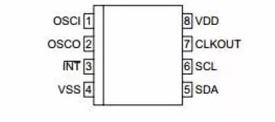
Figure 6.4 PCF85063 pin definition
7 PCF85063 the I 2 C slave address 0x51, MicroPort-RTC interface module is connected via MicroPort AM824-Core, SCL and SDA are connected to PIO0_16 and PIO0_18, see Figure 6.5. If R1 is soldered, INT is connected to PIO0_1; if R3 is soldered, INT is connected to PIO0_8; if R2 is soldered, CLKOUT is connected to PIO0_24.
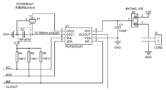
Figure 6.5 PCF85063 circuit schematic
2. Device initialization
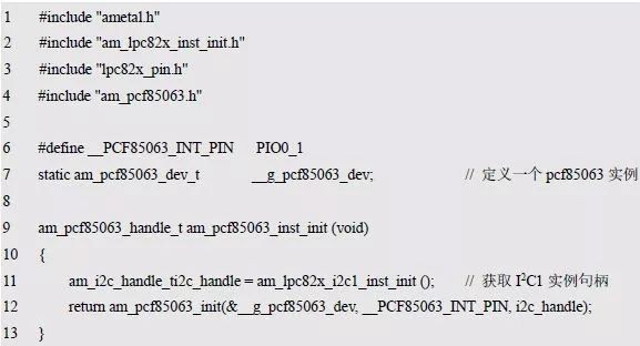
Before using the PCF85063, the initialization of the PCF85063 must be completed to obtain the corresponding operation handle, so that the various functions of the PCF85063 can be used. The initialization function prototype (am_pcf85063.h) is:

This function is intended to obtain the instance handle of the PCF85063 device, where p_dev is a pointer to an instance of am_pcf85063_dev_t type, and int_pin is used as instance information to specify the connection pin number of the INT and MCU of PCF85063.
(1) Example
An example of defining the am_pcf85063_dev_t type (am_pcf85063.h) is as follows:

Where g_pcf85063_dev is a user-defined instance whose address is passed as an argument to p_dev.
(2) Instance information
The instance information has only one interrupt pin information, which is used to specify that the INT of the PCF85063 is connected to the pin number of the MCU, which is convenient for functions such as an alarm clock. Assuming PIO0_1 is used, PIO0_1 is passed as an argument to int_pin.
(3) I 2 C handle i2c_handle
Taking I 2 C 1 as an example, the return value of its instance initialization function am_lpc82x_i2c1_inst_init () is passed as an argument to i2c_handle. which is:

(4) Example handle
PCF85063 initializes the return value of the function am_pcf85063_init () as the argument to the first parameter (handle) of other function interface functions. The definition of am_pcf85063_handle_t type (am_pcf85063.h) is as follows:

If the return value is NULL, the initialization fails. If the return value is not NULL, the return value handle is valid.
Based on the modular programming idea, the definitions of the initialization related instances, instance information, etc. are stored in the corresponding configuration file, and the instance initialization function interface is extracted through the header file. The program examples of the source file and the header file are respectively shown in the program list 6.39 and the program. Listing 6.40.
Listing 6.39 Instance initialization function implementation (am_hwconf_pcf85063.c)
Listing 6.40 Example Initialization Function Declaration (am_hwconf_pcf85063.h)

Subsequent only need to use the parameterless instance initialization function to get the instance handle of PCF85063. which is:

> > > 6.3.2 RTC Universal Interface
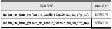
As a typical RTC device, PCF85063 can use RTC (Real-Time Clock) general interface setting and acquisition time. The function prototype is shown in Table 6.10.
Table 6.10 RTC Common Interface Functions (am_rtc.h)
It can be seen that the first parameter of these interface functions is an RTC handle of type am_rtc_handle_t. Obviously, it is not the handle of type am_pcf85063_handle_t obtained by the PCF85063 instance initialization function.
RTC time setting and acquisition is just one of the main functions provided by the PCF85063. The PCF85063 also provides functions such as an alarm clock. The PCF85063 driver provides a corresponding interface for obtaining the RTC handle of the PCF85063, so that the user can operate the PCF85063 through the RTC universal interface. The function prototype is:

This function is intended to get the RTC handle, where the handle of the PCF85063 instance (pcf85063_handle) is passed as an argument to the handle, p_rtc is a pointer to an instance of the am_rtc_serv_t type, with no instance information. The definition of the am_rtc_serv_t type (am_rtc.h) is as follows:

Where g_pcf85063_rtc is a user-defined instance whose address is passed as an argument to p_rtc.
Based on the modular programming idea, the initialization related instance definitions are stored in the corresponding configuration file, and the instance initialization function interface is extracted through the header file. The source file and the header file are respectively shown in the program list 6.41 and the program list 6.42.
Listing 6.41 adds RTC instance initialization function for PCF85063 (am_hwconf_pcf85063.c)
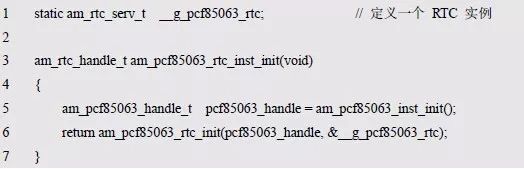
Listing 6.42 am_hwconf_pcf85063.h File Content Update (1)

Subsequent only need to use the parameterless RTC instance initialization function to get the RTC instance handle. which is:

Set time
This function is used to set the current time value of the RTC device. The function prototype is:

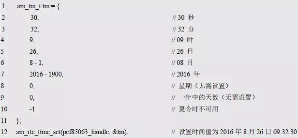
Where handle is the RTC instance handle and p_tm is the pointer to the subdivision time (the time value to be set). Return AM_OK, indicating that the setting was successful, and vice versa. Its type am_tm_t is the subdivision time structure type defined in am_time.h and is used to represent information such as year/month/day/hour/minute/second. which is:

Among them, tm_mon represents the month, corresponding to 1~12 months. Tm_year represents the year, the number of years from 1900 to the present, and the actual year is the value plus 1900. Tm_wday; indicates the week, 0~6 corresponds to Sunday to Saturday. Tm_yday represents the number of days since January 1 (0~365), and 0 corresponds to January 1. Tm_isdst represents daylight saving time and will be adjusted for 1 hour in summer. If not used, set to -1. Set the value of year/month/day/hour/minute/second. See Listing 6.43. Some additional information such as the week does not need to be set by the user. It is mainly convenient to get more information when getting time.
Listing 6.43 Setting the time sample program
2. Get time
This function is used to get the current time value, the function prototype is:

Among them, the handle is the RTC instance handle, and p_tm is the pointer to the subdivision time, which is used to obtain the subdivision time. Return AM_OK, indicating that the acquisition is successful, and vice versa. The sample program is shown in Listing 6.44.
Listing 6.44 Obtaining the Breakdown Time Sample Program

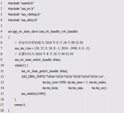
Based on the RTC universal interface, you can write a common time display application: print the current time value through the debug serial port every 1s. The application implementation and interface declarations are detailed in Listing 6.45 and Listing 6.46, respectively.
Listing 6.45 RTC Time Display Application (app_rtc_time_show.c)

Listing 6.46 RTC Time Display Interface Declaration (app_rtc_time_show.h)

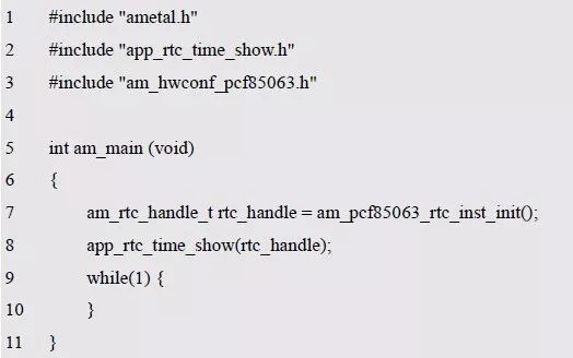
In order to launch the application, an RTC instance handle must be provided to specify the RTC object to set the time and get time. If PCF85063 is used, the RTC instance handle can be obtained by the instance initialization function am_pcf85063_rtc_inst_init(). See Appendix 6.47 for the sample program.
Listing 6.47 Starting the RTC application (based on PCF85063)
> > > 6.3.3 Alarm universal interface
In addition to providing basic RTC functions, the PCF85063 can also provide an alarm function. The alarm clock can be used to set the alarm clock. The function prototype is shown in Table 6.11.
Table 6.11 Alarm Common Interface Function (am_alarm_clk.h)
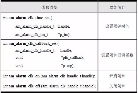
It can be seen that the first parameter of these interface functions is the alarm handle of type am_alarm_clk_handle_t. The driver of PCF85063 provides the corresponding interface for obtaining the alarm handle of PCF85063, so that the user can operate PCF85063 through the alarm universal interface. The function prototype is:
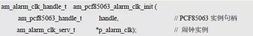
This function is intended to get the alarm handle, where the handle of the PCF85063 instance (pcf85063_handle) is passed as an argument to the handle, and p_alarm_clk is a pointer to an instance of the am_alarm_clk_serv_t type, with no instance information. An example of defining the am_alarm_clk_serv_t type (am_alarm_clk.h) is as follows:

Where g_pcf85063_alarm_clk is a user-defined instance whose address is passed as an argument to p_alarm_clk.
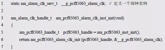
Based on the modular programming idea, the initialization related instance definitions are stored in the corresponding configuration file, and the instance initialization function interface is extracted through the header file. The source file and the header file are respectively shown in the program list 6.48 and the program list 6.49.
Listing 6.48 adds the alarm instance initialization function for PCF85063 (am_hwconf_pcf85063.c)
Listing 6.49 am_hwconf_pcf85063.h File Content Update (2)

Subsequently, you only need to use the no-argument alarm instance initialization function to get the alarm instance handle. which is:

1. Set the alarm time
This function is used to set the alarm time. The function prototype is:
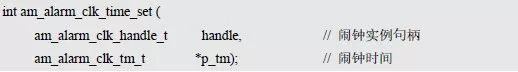
Where handle is the alarm instance handle and p_tm is the pointer to the alarm time (time value to be set). Return AM_OK, indicating that the setting was successful, and vice versa. The type am_alarm_clk_tm_t is the alarm time structure type defined in am_alarm_clk.h and is used to represent alarm time information. which is:
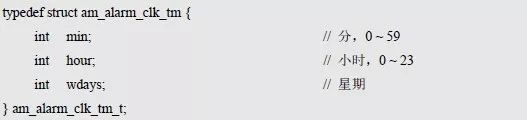
Where min is the hour of the alarm time, hour of the hour of the alarm time, and wdays is used to specify that the alarm is valid on the day of the week, which can be any day or days from Monday to Sunday. Its value is already available using a macro is defined, for example, AM_ALARM_CLK_SUNDAY bit effective Sunday, AM_ALARM_CLK_MONDAY effective Monday, AM_ALARM_CLK_TUESDAY effective Tuesday, AM_ALARM_CLK_WEDNESDAY is effective Wednesday, AM_ALARM_CLK_THURSDAY is effective Thursday, M_ALARM_CLK_FRIDAY is effective Friday, AM_ALARM_CLK_SATURDAY effective Saturday, AM_ALARM_CLK_WORKDAY Valid for weekdays, AM_ALARM_CLK_EVERYDAY is valid for every day.
If the alarm clock is valid for multiple days, you can connect multiple macro values ​​with "|". For example, to make the alarm valid on Mondays and Tuesdays, the values ​​are:
AM_ALARM_CLK_MONDAY | AM_ALARM_CLK_TUESDAY.
If the alarm is valid from Monday to Friday (working days are valid), the value is:
AM_ALARM_CLK_WORKDAY.
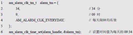
If the alarm clock is valid every day, the value is AM_ALARM_CLK_EVERYDAY, and the sample program for setting the alarm is shown in Listing 6.50.
Listing 6.50 Example program for setting the alarm time
2. Set the alarm callback function
The PCF85063 can generate an alarm event at a specified time. When an event occurs, because the application needs to be notified, it is necessary to set a callback function by the application to automatically call the callback function set by the application when the alarm event occurs. Set the alarm callback function prototype to:
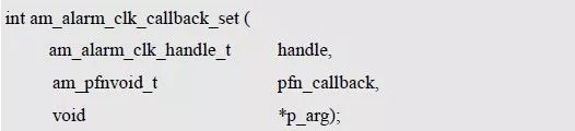
Where handle is the alarm instance handle, pfn_callback is the pointer to the actual callback function, and p_arg is the argument to the callback function. If AM_OK is returned, the setting is successful, otherwise it fails.
The type of the function pointer am_pfnvoid_t is defined in am_types.h, ie:

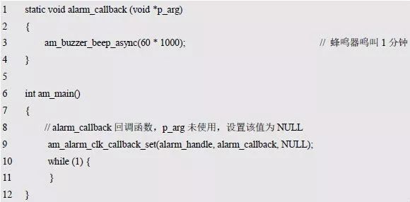
When the alarm event occurs, the callback function pointed to by pfn_callback is automatically called. The parameter of the void* type passed to the callback function is the set value of p_arg. For the sample program, see Listing 6.51.
Listing 6.51 Setting the Alarm Callback Function Sample Program
3. Turn on the alarm
This function is used to turn on the alarm so that when the alarm time expires, the user-set callback function is automatically called. The function prototype is:

Among them, handle is the alarm example handle. Return AM_OK, indicating that the open is successful, and vice versa. The sample program is shown in Listing 6.52.
Listing 6.52 Opening the Alarm Sample Program

4. Turn off the alarm
This function is used to turn off the alarm. The function prototype is:

Among them, handle is the alarm example handle. Returning AM_OK means that the shutdown is successful, and vice versa. The sample program is shown in Listing 6.53.
Listing 6.53 Close Alarm Sample Program

Based on the alarm clock universal interface, you can write a general alarm test application: set the current time to 09:32:30, the alarm time is 09:34, after one and a half minutes, the alarm time is reached, and the buzzer sounds for 1 minute. The implementation and interface declarations for the alarm test application are detailed in Listing 6.54 and Listing 6.55.
Listing 6.54 Alarm Test Application (app_alarm_clk_test.c)
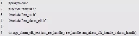
Listing 6.55 Alarm Test Application Interface Declaration (app_alarm_clk_test.h)
In order to launch the application, an RTC instance handle must be provided to set the current time and an alarm instance handle to set the alarm. If PCF85063 is used, the RTC instance handle can be obtained by am_pcf85063_rtc_inst_init(), and the alarm instance handle can be obtained by am_pcf85063_alarm_clk_inst_init() The sample program is detailed in Listing 6.56.
Listing 6.56 Launching the Alarm Test Application (based on PCF85063)

> > > 6.3.4 System time
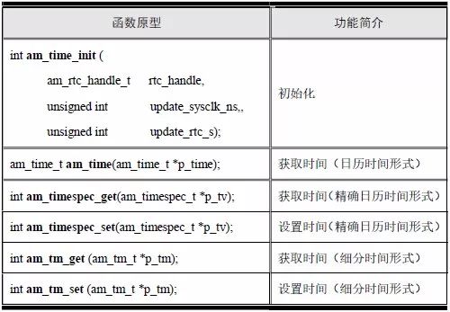
The AMetal platform provides a system time, and the functional prototypes for setting up and obtaining system time are detailed in Table 6.12.
Table 6.12 System Time Interface Function (am_time.h)
System time
The three representations of system time are calendar time, precise calendar time, and subdivision time. The subdivision time has been introduced before. Only calendar time and precise calendar time are introduced here.
Calendar time
The same definition and standard C, the number of seconds from calendar time at 1:00:00 on January 1, 1970 began. Its type am_time_t is defined as follows:

Accurate calendar time
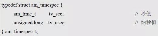
The calendar time precision is seconds, the precision of the precise calendar time can reach nanoseconds, and the precise calendar time is based on the calendar time. A nanosecond counter is added. The type am_timespec_t(am_time.h) is defined as follows:
When the nanosecond value reaches 1000000000, the second value is incremented by one; when the value is reset to 0, it is recounted.
2. Initialization
Before using the system time, the system time must be initialized. The function prototype is:
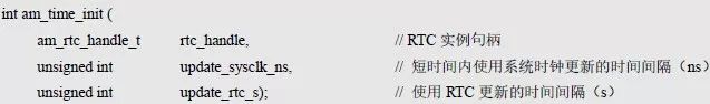
Among them, rtc_handle is used to specify the RTC used by the system time, the system time will use the RTC save time and acquisition time. Update_sysclk_ns and update_rtc_s are used to specify parameters related to updating system time.
RTC handle rtc_handle
The get RTC handle can be obtained through the RTC instance initialization function and passed as an argument to rtc_handle. which is:

Parameters related to system time updates (update_sysclk_ns and update_rtc_s)
Each MCU has a system clock. For example, the LPC824 has a system clock frequency of 30 MHz, often referred to as the primary frequency. In a short time, the error of this clock is small. Since reading data directly from the MCU is much faster than reading data from the RTC device through I 2 C , the time value obtained from the system clock is much faster than the time value obtained directly from the RTC device, which can be short. Use this clock to update the system time during the time, for example, increasing the nanosecond value of the precise calendar time by 1000000 every 1ms. However, if the clock is used for a long time to update the system time, a large error will inevitably occur. This requires re-reading the exact time value from the RTC device at regular intervals to update the system time to ensure the accuracy of the system time.
Update_sysclk_ns specifies the time interval for updating the system time using the system clock. The unit is ns, which is usually set to 1~100ms, which is 1000000~100000000. Update_rtc_s is the time interval for specifying the system time to update the RTC device. If the accuracy requirement is extremely high, set the value to 1, that is, use RTC to update the system time every second. It is usually reasonable to set it to 10~60.
Based on this, the initialization function call is added to the configuration file, and the instance initialization function interface of the system time is extracted by the header file. See Listing 6.57 and Listing 6.58 for details.
Listing 6.57 PCF85063 is used as an instance initialization for system time (am_hwconf_pcf85063.c)
Listing 6.58 am_hwconf_pcf85063.h File Content Update (2)

Subsequently, you only need to simply call the no-argument function to complete the initialization of the system time. which is:

3. Set system time
There are 2 ways to set the system time according to different time representations.
The function prototype for the precise calendar time setting is:

Where p_tv is a pointer to the exact calendar time (the time value to be set). If AM_OK is returned, the setting is successful, otherwise it fails. For the sample program, see Listing 6.59.
Listing 6.59 Using the Accurate Calendar Time to Set the System Time Sample Program
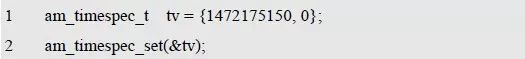
The precise value of the second order 1472175150 calendar time, the value is from at 0:00 on January 1, 1970 seconds 0 seconds to August 2016 09 hours 26 minutes 30 seconds 32. The upcoming time is set to 09:32:30 on August 26, 2016. The time value is usually not set this way, and the time value is set in the subdivision time mode.
The function prototype for the subdivision time setting is:

Where p_tm is a pointer to the subdivision time (the time value to be set). If AM_OK is returned, the setting is successful, otherwise it fails. For the sample program, see Listing 6.60.
Listing 6.60 Using the Breakdown Time to Set the System Time Sample Program
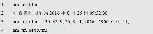
Set the time to 09:32:30 on August 26, 2016. When using the segmentation time to set the time value, the members of the subdivision time tm_wday, tm_yday are updated after the call. Set to -1 if daylight saving time is not used.
4. Get system time
There are three ways to get system time, depending on the time representation.
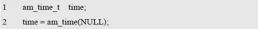
The function prototype for getting the calendar time is:

Where p_time is a pointer to the calendar time used to get the calendar time. The return value is also the calendar time. If the return value is -1, it indicates that the acquisition failed. The sample program for obtaining the calendar time by the return value is shown in Listing 6.61.
Listing 6.61: Get the calendar time sample program with the return value
The calendar time can also be obtained by parameters. The sample program is detailed in Listing 6.62.
Listing 6.62: Getting a calendar time sample program with parameters

The function prototype for getting the exact calendar time is:

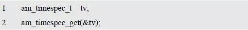
Where p_tv is a pointer to the exact calendar time used to get the exact calendar time. If AM_OK is returned, the acquisition succeeds, otherwise it fails. The sample program is shown in Listing 6.63.
Listing 6.63 Read the exact calendar time sample program
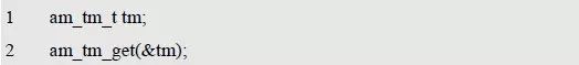
The function prototype for getting the breakdown time is:

Among them, p_tm is a pointer to the subdivision time, used to obtain the subdivision time. If AM_OK is returned, the acquisition is successful, otherwise it fails. The sample program is shown in Listing 6.64.
Listing 6.64 Get the subdivision time sample program
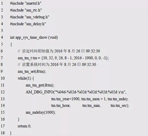
Based on the system time-related interface, you can write a general system time test application: print the current system time value by debugging the serial port every 1 s. The application implementation and interface declarations are detailed in Listing 6.65 and Listing 6.66, respectively.
Listing 6.65 System Time Test Application (app_sys_time_show.c)
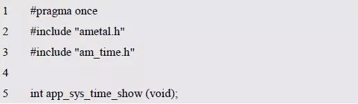
Listing 6.66 System Time Test Application Interface Declaration (app_sys_time_show.h)
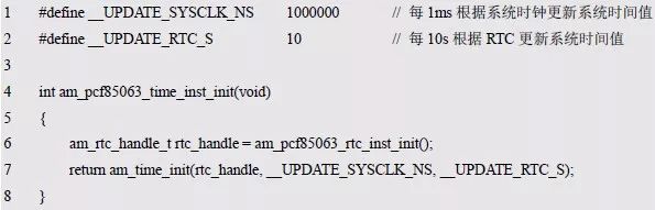
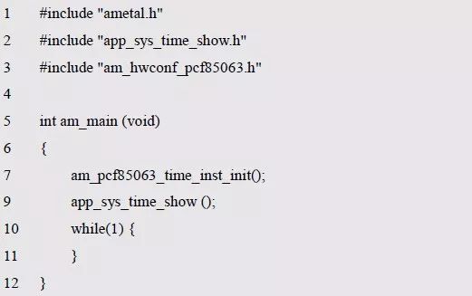
It can be seen that in the application, no instance handle is used, so that the application is not directly associated with any specific device. The definition of the system time makes the application more convenient when it is used. The system time initialization must be completed before starting the application. If the PCF85063 is used to provide the RTC service for the system time, the system time initialization can be completed by am_pcf85063_time_inst_init (). The sample program is shown in Listing 6.67.
Listing 6.67 Starts the system time test application (based on PCF85063)
> > > 6.3.5 Special function control interface
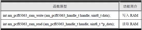
For the PCF85063, in addition to the typical clock and alarm functions, there are special features such as timers, clock outputs, 1-byte RAM, and more. These functions are not universal functions and can only be operated using the corresponding interface of the PCF85063. Take the read and write 1 byte RAM as an example, the corresponding interface function is shown in Table 6.13.
Table 6.13 Reading and Writing RAM Interface Functions (am_pcf85063.h)
1. Write to RAM
This function is used to write 1 byte of data into the RAM of the PCF85063. The function prototype is:

Where handle is PCF85063 instance handle and data is single byte data written. If AM_OK is returned, the data is written successfully, otherwise it fails. The sample program written to 0x55 to RAM is shown in Listing 6.68.
Listing 6.68 Write RAM Sample Program

2. Read RAM
This function reads the data stored in the single-byte RAM of the PCF85063. The function prototype is:

Among them, handle is PCF85063 instance handle, p_data is output parameter, used to return the read single-byte data. Return AM_OK, indicating that the reading was successful, and vice versa. The sample program is shown in Listing 6.69.
Listing 6.69 Reading the sample program

You can use the read and write RAM interface to verify that the PCF85063 is normal. See Listing 6.70 for details.
Listing 6.70 Read and write RAM data sample program

All In One Pc,All In One Pc Gaming,All In One Pc As Monitor,All In One Pc For Business
Guangzhou Bolei Electronic Technology Co., Ltd. , https://www.nzpal.com