introduction
Cars have made outstanding contributions to the development of human society, but they have also brought shocking injuries. In recent years, with the development of expressways, the speed of cars has increased, and vicious traffic accidents have occurred frequently. In the fatal accident caused by a car accident, the rear-end accounted for 25%. Therefore, research can obtain road and vehicle information at any time, and promptly remind car drivers to take measures to avoid dangerous distance monitoring and early warning system has become an important means to solve road traffic safety problems.
Based on RFID and satellite navigation technology, this paper realizes the mutual communication between vehicles. By reporting the precise geographical information of the vehicle to surrounding vehicles and obtaining the geographical information transmitted by surrounding vehicles, the vehicle distance is calculated in real time.
Compared with other implementation schemes such as radar ranging, this scheme has the advantages of low cost, simple structure and high precision.
1 Introduction to RFID and satellite navigation technology
RFID technology first appeared in World War II, when it was successfully applied to the aircraft's enemy-identification system. It has now developed into one of the most important technologies of the 21st century. The basic principle is to realize the automatic identification of the identified object by utilizing the spatial coupling (inductive or electromagnetic coupling) or reflection transmission characteristics of the radio frequency signal.
The satellite navigation technology was first applied to the Global Positioning System (GPS) jointly developed by the US Army, Navy and Air Force in the 1970s. It has been used globally for civilian use. Since the position of the satellite is accurate, in the GPS observation, we can get the distance from the satellite to the receiver, apply the distance formula in the three-dimensional coordinates, and use three satellites to form three equations to solve the position of the observation point (X , Y, Z), to determine the location of the object.
2 system overall design
The system design includes single chip control module, radio frequency communication module, satellite navigation module, liquid crystal display module, sound and light alarm module and regulated power supply module. The system uses the LM1575 chip to convert the vehicle 12V power supply into a 5V power supply. The Sunplus SPCE061A 16-bit single-chip microcomputer is used as the control center. The nRF2401 wireless RF transceiver module is used to transmit and receive data. The OTrack-32 Beidou/GPS/GLONASS multi-mode is compatible. The navigation chip module realizes the acquisition of the latitude and longitude coordinates, and simultaneously displays the vehicle distance detection information in real time using the 12864 LCD display module, and realizes the sound and light alarm using the buzzer and the LED. The system block diagram is shown in Figure 1.
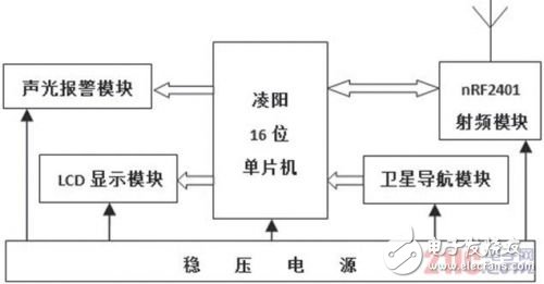
Figure 1 system overall frame diagram
When the system works, first obtain the precise latitude and longitude information of the vehicle through the satellite navigation chip, and then encode the information. The coding information mainly includes the vehicle identification serial number, latitude and longitude information and vehicle speed [3]. After the information is encoded, the coded information is sent through channel 1 of the radio transceiver module, and the receiving address should be set to a unified public address. This design specifies a 5-digit hexadecimal address: 0xAAAAA. At the same time, channel 2 is used to receive the information sent by the surrounding vehicles, and the received information is sent to the single chip for processing.
When a communication collision occurs in the information received by multiple radio frequency modules at the same time, the RFID anti-collision algorithm is used for processing. The single-chip microcomputer continuously receives the vehicle identification serial number, the latitude and longitude information and the vehicle speed from the RF transceiver module, and performs data structure queue sorting processing on the information according to the vehicle serial number.
The vehicle's distance measurement algorithm and the vehicle's driving direction determination algorithm are used to obtain the driving direction and distance of each vehicle in real time. The vehicle distance between the surrounding vehicles and the safety distance corresponding to different vehicle speeds are compared. When the vehicle distance is less than the safety distance, the driver is alerted by sound and light.
3 system hardware design
3.1 Microcontroller
SPCE061A is a 16-bit microcontroller produced by Taiwan's Sunplus Technology. It uses the μ'nSPTM series of microcontroller cores with embedded 32k words of flash memory. It has a high processing speed and can be applied not only to traditional control applications. It can also be extended to control processing, data processing, and digital signal processing, and has a wide application space. The system uses the Sunplus MCU as the control center to realize the control of the RF transceiver module, satellite navigation module, LCD display module and sound and light alarm.
3.2 RF transceiver module
The nRF2401 chip is a single-chip wireless RF transceiver chip that operates at 2.4 GHz, enabling simultaneous data transmission and two-way data reception.
It integrates RF, 8051MCU, 9-channel 12-bit ADC, peripheral components, inductors and filters all in a single chip, with very low power consumption, output power and communication channels can be configured through the program, and the application range is very wide. The nRF2401 module with nRF2401 chip as the core has two sets of interfaces, which use interface 1 to send data respectively; interface 2 receives data to realize bidirectional transmission of information.
3.3 Satellite navigation module
The satellite navigation module required by this system adopts the satellite navigation chip Otrack-32 produced by Beijing Oriental Lianxing, which can simultaneously receive the Beidou II, GPS, GLONASS satellite signals, and realize multi-system joint navigation positioning, speed measurement and timing. Otrack-32 chip realizes the fastest 1s hot start in the world, the shortest 35s cold start in the world, stable 1s re-capture; up to 20 true-value positioning per second; positioning accuracy 5m; differential positioning accuracy 0.5m; high Reliable, anti-interference; adapt to harsh environments; passed strict ground testing and a variety of carrier dynamic tests. The Otrack-32 chip provides a fully localized high-performance core device for professional navigation in navigation, measurement, and timing.
3.4 12864 LCD Module
The system adopts 12864 dot matrix LCD display module, which can display related information such as surrounding vehicles, minimum distance, and latitude and longitude of the vehicle. The dot matrix LCD display module not only displays frequently used characters, but also displays graphics and Chinese characters.
The 12864LCD display module displays 128 points in the horizontal direction and 64 points in the vertical direction. It can display 16&TImes at the same time; 16 Chinese characters, 4 lines and 8 columns, which can meet a large number of information display requirements. The module pin connections are shown in Figure 2.
3.5 sound and light alarm circuit
When the distance between the vehicles is relatively close, the signal is output through the single-chip microcomputer to make the sound and light alarm work. The system uses an LED and a buzzer to realize the sound and light alarm, and uses two MCU output ports to realize the control of the LED and the buzzer respectively.
The circuit principle is shown in Figure 2.
4 system software design
When the system works, first perform system self-test and initialization settings, and display the “Welcome†interface through the LCD module. Then, the latitude and longitude information is received by the satellite navigation module and input to the single-chip microcomputer. The single-chip microcomputer transmits the latitude and longitude information through the channel 1 of the nRF2401 module by controlling the radio frequency transceiver module, and simultaneously receives the latitude and longitude information around the channel 2, and receives the latitude and longitude information of the surrounding vehicles. Input to the microcontroller for processing.
The distance between the two vehicles is calculated by the latitude and longitude of the two vehicles through the ranging speed measurement model, and the distance between the two vehicles is compared with the safety distance. If the distance is smaller than the safety distance, the relative driving direction and the front and rear directions of the vehicle are determined. In the same direction and less than the safe distance, the single-chip microcomputer controls the LED light to flash. The smaller the distance, the faster the blinking frequency of the LED light, and the buzzer is controlled to sound an alarm.
The system software flow is shown in Figure 4.
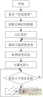
Figure 4 system software flow chart
5 algorithm model
5.1 Car Ranging Velocity Model
The information received by the RF transceiver module is mainly latitude and longitude information. The system can dynamically process the information and the real-time latitude and longitude information of the vehicle to obtain the latest distance information at each moment. First, the latitude and longitude information is formatted. The latitude information is defined as "positive (+)" in the north latitude and "negative (-)" in the south latitude; "positive (+)" in the longitude information and "negative (-)" in the west. The circumference of the earth is about 40008km. Then the average latitude of 1 degree is approximately equal to 111km. The accuracy of the latitude and longitude information collected by the system is 0.0001, and the representative distance per one ten thousandth unit is approximately equal to 11.1m, which can meet the system precision requirements. Thus, a general ranging model is available:
![]()
Among them, E1 and E2 respectively represent the longitude information of the vehicle and other vehicles, W1 and W2 respectively represent the latitude information of the vehicle and other vehicles, and a represents the length of the latitude and longitude of 1°, about 1.11 & TImes; 105m. For special cases, such as the 180° east longitude and the west longitude 180° boundary area, longitude conversion processing is required before the calculation. For the calculation of the vehicle speed, the above-mentioned ranging model can be used to calculate the latitude and longitude measured by the vehicle, and the vehicle moving distance in the latitude and longitude scanning period T of the satellite navigation chip is obtained, thereby obtaining the vehicle speed v.
5.2 Vehicle driving direction determination model
In the actual situation, the direction of the surrounding car is mainly in the same direction and opposite direction as the car. In both cases, the latitude and longitude change direction is completely opposite. Then, the latitude and longitude information matrix of a certain vehicle at multiple times is [A1, B1], [A2, B2]...[An, Bn], by judging the positive and negative of [An, Bn], and with [An-1, Bn] The value of -1] is compared to determine the approximate direction of travel. Using matrix

It indicates the direction of travel of the car, where E, W, S, and N indicate the east, west, south, and north directions, respectively. Let the direction of the car heading is 1. If the other cars are in the same direction as the car, the matrix of the two cars will be subtracted to obtain the zero matrix. By judging the zero matrix, the relative driving directions of the surrounding cars and the vehicle can be roughly obtained, and the directions of the surrounding cars in front and rear of the vehicle can be known.
6 system test
System testing and acceptance testing focus on verifying the rationality of the design and verifying the functionality and reliability of the system. For the test of this design, it mainly carries out four aspects: circuit principle test, system hardware module test, software system test and hardware and software joint debugging.
(1) Power supply module test. Connect the power output to the oscilloscope and observe the voltage fluctuation range within the system requirements to meet the system application requirements.
(2) The 12864 LCD display module is tested to realize the display of characters, Chinese characters and specific images, and the module test is correct.
(3) Satellite navigation module test. The program is written into the single-chip microcomputer, and the satellite navigation module is connected, and the received data is displayed on the LCD display, and the display result is stable.
(4) RF transceiver module test. Connect the single-chip microcomputer, use two sets of modules to send and receive tests, all send and receive information correctly.
(5) Sound and light alarm module detection. The module has a good electrical connection. The program for detecting the sound and light alarm is written into the single chip microcomputer, and the module can normally emit the sound and light signal.
7 Conclusion
The system uses satellite navigation and RFID technology to achieve the distance measurement. Through debugging, the system runs normally and achieves the expected goal. However, there are still many areas that need further exploration, such as the accuracy of satellite navigation and the longer-distance communication of RFID. Due to limited conditions, testing has only been carried out in the laboratory, and further research is needed on anti-interference tests.
Toaster, is a commonly used kitchen supplies, mainly used to bake bread. A toaster usually includes a multi-functional oven, a heat-insulating surface, a special lifting device, etc. The more advanced also includes a separable breadcrumb chassis. The toaster is a heating appliance. Its function is to generate enough heat in the vicinity of the bread to bake the bread. If there is no pop-up toaster, breakfast will certainly not be so rich nowadays.
In many families, the toaster is more prone to failure than any other small home appliance. There are two reasons for this. First of all, the toe machine manufacturing costs are generally very low, its quality is not high. You can replace a new device with just $ 10.
Second, the toaster is often not a problem when their own failure, but the food particles interfere with its normal operation. If there are too many slices of bread on the bracket, they will fall into the bottom of the toaster and accumulate when the movement of the tray will move up, thus hindering the movement of the bracket, causing the heating element to short circuit, Open the device and affect the function of the spiral tube.
Most of the pop-up toasters are equipped with a large debris plate and have a door at the bottom, the reason for this. By sliding or opening the broken door, you can clean up the food particles that accumulate at the bottom of the toaster.
Electric Bread Maker,Home Bread Maker,Automatic Bread Maker,Portable Bread Maker
Ningbo APG Machine(appliance)Co.,Ltd , http://www.apgelectrical.com