[Guide] When considering the relationship between distribution network (PDN) impedance and simultaneous switching noise (SSN) and electromagnetic compatibility (EMC), it is important to understand the effects of decoupling. If a PCB has poor power integrity or decoupling characteristics, such as high PDN impedance, SSN and EMC issues can arise. This article will demonstrate the relationship between PCB PDN impedance, SSN and EMC through actual cases.
This paper confirms the relationship between PCB PDN impedance, SSN and EMC through actual cases.
Understanding the effects of decoupling is critical when considering the relationship between distribution network (PDN) impedance and simultaneous switching noise (SSN) and electromagnetic compatibility (EMC). If a PCB has poor power integrity or decoupling characteristics, such as high PDN impedance, SSN and EMC issues can arise. This article will demonstrate the relationship between PCB PDN impedance, SSN and EMC through actual cases.
Analysis and results
The prototypes tested were the following two versions: an FPGA with an external 50 MHz reference provided by a crystal oscillator; three main interfaces: a 350 MHz clock rate DDR2 SDRAM, a 150 MHz ADC data bus, and a 100 MHz Ethernet. All of these components are powered by a 1.8V step-down converter. The test cases listed in Table 1 show the effects of decoupling (including PCB stacks and capacitors) on SSN and EMC.
In Test Case 1, the prototype PCB consisted of four signal layers and a ground plane with 16 0.1μF decoupling capacitors connected to the +1.8V supply pins of the FPGA on the PCB. In Test Case 2, the prototype PCB consisted of four signal layers and three ground planes with 25 0.1μF decoupling capacitors connected to the +1.8V supply pins of the FPGA on the PCB.
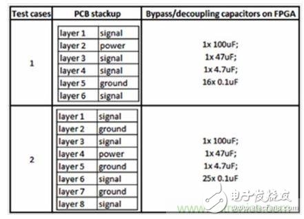
Table 1. Test cases to study the effects of PCB decoupling on SSN and EMC.
It can be seen from the PDN impedance curve of Figure 1 (using Mentor Graphic Hyperlynx software to analyze the power integrity of the post-layout). Compared to Test Case 1, the power grid of Test Case 2 has better decoupling conditions and thus is in the broadband range. There is a lower impedance inside. A 0.1μF capacitor can have an effect in the mid-low frequency range (< 400MHz). In addition, the planar capacitance of the ground plane has an effect at frequencies above 400 MHz. Compared to Test Case 1, Test Case 2 has more decoupling capacitors and ground planes and thus has a lower PDN impedance.
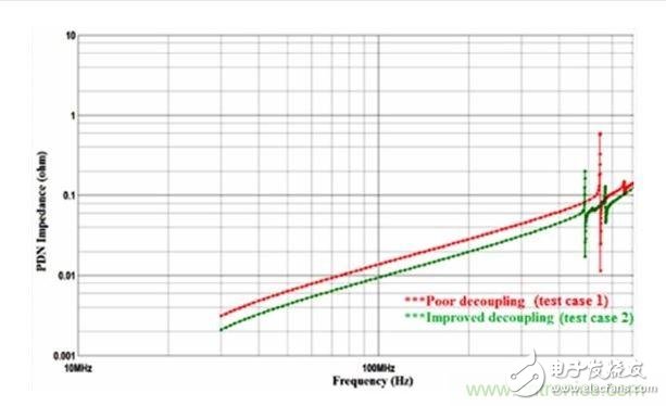
Figure 1. PDN impedance map
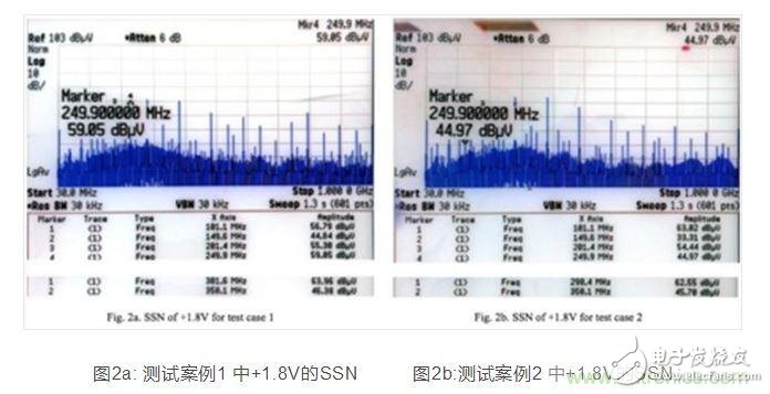
Then, the power spectra of the +1.8V (using the spectrum analyzer through AC-coupled detection) across the 30MHz to 1000MHz frequency were compared between the two test cases. Referring to the spectrum of Test Case 2 shown in Figure 2b, the observed spurs are mainly composed of crystal oscillator (50MHz fundamental frequency), DDR2 SDRAM (350MHz fundamental frequency), ADC data bus (150MHz fundamental frequency) and Ethernet ( Caused by harmonics of 100MHz fundamental frequency). In Test Case 1 shown in Figure 2a, due to poor decoupling performance, spurs appear in the spectrum and its power is highest.
The interaction between the PDN impedance and the crystal oscillator transient current, coupled with the IC output buffer (ie, SSN) that simultaneously switches or switches at a particular frequency, creates grid noise. By improving the decoupling to reduce the power impedance, SSN and frequency spurs can be suppressed.
The noise performance between the prototypes of the two test cases can be compared by performing a radiation emission (RE) test in a 3 meter anechoic chamber. Test Case 2 shows better RE or EMC performance than Test Case 1, and Test Case 2 has more ground planes, which not only improves decoupling or PDN impedance, but also provides for all signals transmitted along the PCB trace. Proper return path further reduces radiation emissions.
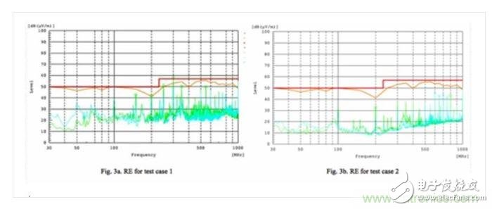
Figure 3a: RE of test case 1 Figure 3b: RE of test case 2
in conclusion
Practical tests have confirmed that decoupling does have an impact on SSN and EMC. Therefore, PDN and PCB stacks must be performed in a rigorous manner to ensure excellent quality, robustness, and functionality.
Back Seat Headrest Pillow Phone Holder
Back Seat Headrest Pillow Phone Holder,Samsung Tablet Car Holder Back Seat,Car Back Seat Organiser With Tablets,Car Back Seat Tablet Holder
Ningbo Luke Automotive Supplies Ltd. , https://www.nbluke.com