The flight we took was just beginning to drop, and a gentleman sitting next to me turned to talk to me about engineering—he saw me reading an engineering journal. The neighbor's husband said that he is a member of the Institute of Electrical and Electronics Engineers (IEEE), and his original ambition is to be a member of a standards committee. I asked him which standard work was being worked on - it was related to plant safety. It was not until the plane stopped in front of the terminal that we ended the conversation and then parted ways. During the discussion, I talked about the importance of standards and told him from the perspective of my industry. How surprised I was that we didn’t have an IEEE standard until 2000 to standardize and test analog-to-digital converters (ADCs). The method is defined.
This is worthy of our attention, because at least in the 1920s, analog-to-digital conversion was well known, and commercial ADCs appeared in the 1960s [1]. For decades, ADC manufacturers have defined the specifications for these devices and tested them individually and independently. Naturally, there are some “standards†about how to test, but there are still no standard guidelines issued by the physical standards body.
The first real ADC standard development work began in 1980, and finally released the IEEE1057 [2] standard, which is later IEEE1241 [3]. The IEEE1241 is specific to the ADC device itself, which is completely different from a complete set of data acquisition or recording systems. IEEE1241-2000 is the first standard to be truly developed for ADC component manufacturers; the standard was updated in 2010.
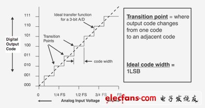
Figure 1 The ideal ADC transfer function evenly arranges each transition point
(width is just a least significant bit LSB)
The main task of the ADC evaluation is to determine its transfer function. Ideally, a converter has a transfer function similar to that shown in Figure 1. Figure 1 shows the transfer function of a three-bit converter. In an ideal converter, the width of each code is exactly the same, and you can draw a straight line through the midpoint of each code "plateau." In fact, this is not always the case—because the actual transfer function is different from the ideal case, determining the transfer point and code width is critical for ADC testing and characterization.
In order to find a true transfer function, the IEEE standard recommends several possible test steps and methods. One approach is to utilize a complex servo loop system that requires a digital-to-analog converter (DAC) with a higher resolution than the ADC under test. Another method is to use a sine wave oscillator, but must have a total harmonic distortion and noise (THD+N) that is at least 20 dB higher than the expected signal to noise ratio (SINAD) of the ADC being tested. For example, an ideal 16-bit ADC has a signal-to-noise ratio (SNR) of 98 dB and no distortion (after all, it is ideal) - then SINAD is 98 dB. To test this ADC, an oscillator with THD+N above –118dB is required. When you look at a high resolution ADC, if the sine wave generator cannot perform the task alone, it may require filtering to obtain a pure spectral signal.
Finding such high-resolution DACs or pure-spectrum oscillators and creating the complex test equipment required, they are willing to do so for the majority of ADC manufacturers, and generally have such capabilities. Some of these instruments are expensive, but if your business is to make ADCs, then these investments are worthwhile. But for those individuals who are working on ADC system design, how do they perform ADC evaluation and testing?
Many people will switch to the evaluation boards and tool kits provided by the manufacturer (Figure 2) for testing. With these systems, we can easily connect the ADC under test to a computer via a USB cable, then use the software to collect the data and finally analyze it.
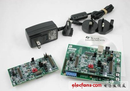
Figure 2 Evaluation boards and tool kits from ADC manufacturers (eg TI ADS1281EVM-PDK, etc.) usually have a complete data acquisition system but lack a signal source. The software provided typically performs tests similar to the IEEE standard.
Some people want to use the evaluation kit to get the same results as the ADC product specification, but not every time, especially when using a high-resolution converter, because the required sine wave generator may not be available. Despite the use of evaluation boards and their software, you can often get some meaningful results, but be cautious.
Evaluation hardware and analysis software generally work in a mode called "block mode." In this mode, a fixed number of samples are collected and sent to the software, which then analyzes the data block or data record. We define most of the IEEE standard tests so that they can process these blocks of data.
The question is, can the tests listed in IEEE1241 really help you evaluate the ADC's applicability? If you believe it can, what else can you get in addition to what you see in the device data sheet? Many people It is believed that in addition to seeing the actual running device, the evaluation board also introduces the reference design and layout, which can be used to guide you in the actual system.
Still, for some people, the IEEE1241 test is not what they need. Depending on the ADC type, some people would like to use the evaluation board and software as a digital oscilloscope or graphics recorder to continuously generate data streams, unlike block-by-block data transfers. Some of the customers I've worked with are trying to figure out long-term stability or drift performance, and they sometimes ask for hours or even days of data to be recorded on the hard drive. Although these applications are more standardized by IEEE 1057, none of them explore long-term drift or stability testing.
Most manufacturers' evaluation boards and software will not support such applications or tests. Should ADC component manufacturers enable their evaluation boards and software to generate data streams and block acquisitions, and turn on other features for testing without specification in ADC-related standards?
For ADC manufacturers, the standard is absolutely relevant. But as circuit designers using these ADCs, the same standards used by ADC manufacturers may not be of much use to you. What criteria do you think of when evaluating ADCs? I will share them with readers in subsequent articles.
Brighten up your life with this Led Neon Signs. This piece gives the attention-getting look of the traditional neon sign with more durability and less energy consumption using the latest LED Technology. Whether it is shining bright or serving as a sculptural statement, this decorative neon lights will always give a room something to say. The LED neon signs are easy to hang with the perfectly placed holes and clear acrylic structure, you`ll have this edgy and practical piece up on your wall in no time.
Led Neon Signs,Led Decorative Neon Lights,Neon Window Signs,Decorative Neon Rope Lights
Shenzhen Oleda Technology Co.,Ltd , https://www.baiyangsign.com