1 Introduction
This article refers to the address: http://
At present, in the field of control, the application of virtual instrument systems is limited to the point-to-point mode of acquisition-feedback-control. For multi-motor systems, especially multi-motor-driven battery vehicle systems, it is necessary to implement a large number of information acquisition, distributed coordinated control, real-time reaction speed and other functions. The traditional method is complicated in hardware, complicated in routing, inconvenient to debug and install, difficult to expand, and does not take advantage of virtual instruments. Therefore, this paper proposes a design scheme of virtual instrument system based on CAN (Controller Area Network) bus, which will communicate with computer. The concept of fieldbus technology and virtual instrument is well combined, and a distributed monitoring system with simple structure, high real-time performance and high scalability is designed. Real-time control and monitoring of multiple motors is realized in complex control systems. Adjust and control the digitization and graphics of effects.
2 Proposal of the overall plan
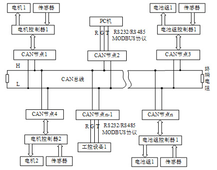
Figure 1 System block diagram
The design system principle is based on the principles of practicality, reliability, and economy, ensuring that the system not only meets the application needs, but also has flexibility, scalability, and versatility. The system is composed of virtual instrument technology, Modbus bus protocol and CAN bus optimization. The schematic diagram of the system is shown in Figure 1. The system uses a PC to monitor multiple motors, multiple sets of batteries and other auxiliary equipment. It is mainly composed of upper computer, battery management system, motor control system and other auxiliary control systems. Each controller communicates through the CAN bus to realize the transmission and reception of control commands, the sharing of sensor measurement data, etc., thereby improving the control performance of the system.
The motor controller realizes the functions of collecting the armature current of the motor, the motor speed, judging the working condition, receiving the set speed, etc. The battery management controller realizes the functions of collecting the battery temperature, voltage, current, and receiving control commands. The upper computer is written in the graphical programming language LabVIEW. The program displays the motor speed, vehicle speed, and the state of charge of the battery in real time in the form of a virtual instrument, and controls the state of the motor battery by operating the upper machine to send control commands. The CAN node is the core part of the system, through which the discrete parts are connected into a unified system. Each CAN node uses a unified hardware platform to achieve different working modes. Each node can independently select the connected device and working mode.
3 CAN node hardware design
For the automotive electronic control unit, in order to simplify the design and improve reliability, an integrated microprocessor with a CAN bus controller is used. The microprocessor with CAN bus controller does not occupy the port resources of the processor, which can greatly simplify the design of the interface circuit, reduce the complexity of the program, and improve the stability of the system. This system uses Philips' high-performance microcontroller P87C591. . Figure 2 is a functional block diagram of the node hardware design. The node function requirements and the selected microprocessor resources are described as follows:
(1) Full-duplex enhanced UART with programmable baud rate generator to complete RS232/RS485 communication according to the specified Modbus protocol; in hardware implementation, RS485 bus terminal uses transceiver MAX481; RS232 bus terminal The transceiver MAX232 is used. In order to realize the switching of the serial port, a jumper slot is specially set in the system for manual selection, and the corresponding data channel is selected by setting different input signal values.
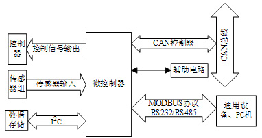
Figure 2 node hardware functional block diagram
(2) Microprocessor P87C591 integrates and enhances the functions of SJA1000 (independent CAN controller) on-chip, fully compatible with CAN2.0 protocol, and can complete communication tasks such as CAN bus data transmission and reception; CAN interface circuit uses CAN bus transceiver PCA82C250, in order to increase the reliability and anti-interference ability of the system, add corresponding opto-isolation circuit between P87C591 and PCA82C250.
(3) The 10-bit ADC with 6 analog inputs can be set as an 8-bit fast ADC, which can basically meet the accuracy requirements of the system for the acquisition, complete the measurement task for the motor and battery status; for the acquisition of analog signals, The acquisition circuit modulates (filters, amplifies, and converts the electrical signals of each test point sensor) into the ADC interface of the microprocessor. To suppress common mode interference, the amplifier basically uses a differential input.
(4) Two 8-bit resolution pulse width modulation outputs (PWM) provide control signals to the motor controller to complete the adjustment of the motor speed. Programmable I/O ports (quasi-bidirectional, push-pull, high-impedance, and open-drain) compatible with the 51 Series provide a channel for digital signals and are responsible for reading and setting switching quantities.
(5) 16K bytes of internal program memory, which can satisfy the program space of this system. The I2C bus serial I/O port with byte mode master and slave functions can be easily interfaced with the peripheral memory chip to realize data storage function.
In addition to the above main parts, the hardware part has a power supply circuit, an expansion memory, and a watchdog circuit. The power circuit provides the required isolated power supply to improve the stability and security of the node; the E2PROM stores certain parameters of the system through the I2C serial bus; the watchdog circuit mainly ensures the stability of the system operation, and is powered on and off. Reset output in case of power and alarm.
4 system software design
4.1 PC software design
The virtual instrument software is mainly divided into three levels: user application layer, virtual device driver layer and hardware device driver layer. The user application layer is closely related to the user's needs. It mainly accomplishes two tasks: 1. Providing the user with a virtual interface of various test instruments, and performing human-computer interaction, which is also known as the interface design, through which the collected measured data is displayed. And status information, providing an interactive platform between the user and the system; second, completing the tasks of classifying, judging, processing, serial communication, and data access operations.
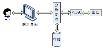
Figure 3 schematic diagram of the host computer program
The serial port device driver is completed by VISA. The VISA provided by LabVIEW is the virtual instrument software architecture (Virtual Instrument Software Architecture). VISA is an interface library for controlling VXI, GPIB, RS232, and other types of instruments on all LabVIEW work platforms. VISA is the standard adopted by the 35 largest instrumentation companies that make up the VXI plug&play system alliance. With the VISA standard, driver software can be used interchangeably regardless of time and instrument I/O options.
4.2 node programming
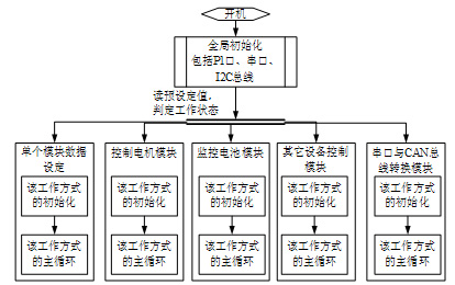
Figure 4 node main block diagram
Figure 4 is the main block diagram. It describes the basic flow of the general-purpose module design. The function of the module and the working mode of the module are determined according to the state of the read-in jumper and the state set in the read-in memory. After the working mode is selected, re-initialize each other, including I/O port configuration, CAN interrupt setting, acceptance filter setting, serial port working mode setting, timer mode setting, baud rate setting, and serial I2C. Related settings. After completing the initial setup, you can return to the working state and enter their respective main loops. The following describes the implementation of each working method:
1) Implementation of bus conversion
The design of the universal serial port to CAN interface conversion mode is mainly to realize the interconnection communication between the CAN bus data and the RS232/485 bus data and the system upgrade. The built-in CAN controller controls the bus working state, and combines the software design to realize the purpose of communication between the universal serial port and the CAN interface. Modbus specifies two transmission modes, ASCII or RTU. The system chooses to use RTU mode. When the Modbus protocol message and the CAN bus message are converted into each other, since the standard CAN protocol has an 11-bit ID, and the address of the Modbus protocol is one byte, the ID is divided into three parts and three parts in order to facilitate conversion. The 3 bits are used to determine the type of the message, and the last 8 bits are the ID value of each module. For example, when the 11-bit Modbus protocol message is forwarded to the CAN port, the conversion format is as shown in FIG. 5. When the CAN bus is forwarded to the serial port, it needs to go through three processes of collecting, queuing and forwarding. The collection is because the return frame of the operation of the host computer sometimes returns the number of multiple nodes.
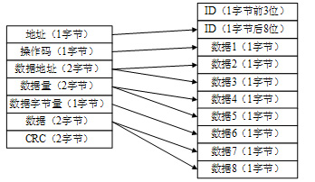
Figure 5 Modbus 11-bit message converted to CAN standard frame
According to the CAN, the serial bus must also notify the time-sharing and receive the data of each node that specifies the return value. The queuing is because if there is a return request from the host computer, the data is sent first, other data is temporarily stored, sent back and then sent, otherwise the returned value is considered to be wrong. The queued data is sent to the host computer in turn.
2) Implementation of monitoring motor
This working mode completes the monitoring of the motor. First, the initialization includes (serial port shutdown, I2C setting, CAN initialization, setting the receiving filter), and reading the setting parameters to enter the main loop. The node is an intelligent node, and has the ability to independently control the operation of the motor. The host computer is only responsible for sending the switch quantity of the control relay to the switch and the digital quantity of the set motor speed. After receiving the node, the motor will automatically adjust the motor to the set. The fixed working rate, which can greatly reduce the bus burden and improve the real-time performance of the system. As the intelligent node itself is responsible for adjusting the motor according to the preset control algorithm, it also shoulders the work of collecting the motor running state (current, voltage, temperature, speed), judging the abnormal state, and transmitting data in real time.
3) Monitoring battery implementation
The motor is driven by the electrical energy provided by the battery. The state of the battery not only reflects its working state but also indirectly reflects the operating state of the motor. The current, voltage and temperature of the battery have their respective thresholds. Under normal operating conditions, each node sends its own state to the host according to the specified timing. When it is in an abnormal working state, the module determines the cause of the problem and takes the corresponding Measures and timely report to the upper computer through the CAN bus. If it is an unrecoverable communication error, the communication cannot be continued. The node automatically completes the task of shutting down the battery and the motor. The drive automatically exits the work and the motor is in a floating state to ensure that the normal running vehicle is not obstructed.
4) Implementation of module settings
According to the setting of the jumper, when the program is turned on, it will judge when to enter the set working mode. When the user needs to set a certain node, the upper computer runs the setting software, the upper computer and the module are connected through the serial port, the node enters the setting working mode (this mode is set one by one for a single module), and the upper computer sends the corresponding function code to read. Take the module parameters and send the corresponding function code to modify the module parameters. The module parameters that can be set include the address of the module, the device connected to the module, the baud rate of the serial port and device communication, etc. These parameters are stored in the memory of the I2C interface.
5) Implementation of other standard equipment
Modbus protocol is an open protocol developed by MODICOM for many manufacturers. The standard Modbus is RS-232C compatible serial interface. The serial communication of this module is to follow the Modbus protocol, so there is more flexibility in the expansion, as long as The upper computer has a certain program corresponding to it, and the industrial control equipment conforming to the Modbus protocol can be easily attached to the CAN bus through this module.
5 Conclusion
The design idea of ​​combining bus technology and virtual technology makes the system function division clearer, the device function realization is more clear, the external connection of the device is more concise, and the system expansion and integration is easier. The generalization of the software platform, the standardization of the software protocol, and the unification of the hardware structure are realized, thereby ensuring the portability and scalability of the system, and providing a new idea for the design of the monitoring system. The actual operation of the system shows that the system design idea is correct, and the system real-time, stability and flexibility can meet the design requirements of the vehicle.
The author of this paper innovates: The virtual instrument technology, Modbus protocol and CAN bus form a unified system, and meet various functional requirements on a unified hardware platform.
Solar Racking System,Energy Ground Brackets Kits,Ground Solar Rack System
Roof solar Mounting System Co., Ltd. , http://www.nssolarsystem.com