An efficient communication network is a major component of the Distributed Advanced Driver Assistance System (ADAS). Analysis of such systems in different scenarios under different system parameters is a very complex task. It is important to evaluate critical system parameters at an early design stage to achieve optimal system behavior. This article will discuss a virtual prototype-based evaluation architecture that can be used to evaluate advanced driver assistance systems based on MOST.
This article refers to the address: http://
The number of advanced driver assistance systems (ADAS) in automobiles is increasing. These systems process information from a variety of sensors, such as radar sensors, cameras or Global Positioning System (GPS), and then help with driving. Because these sensors are distributed throughout the vehicle, an efficient data communication network is needed to share information between different ADASs. In addition, these systems often require processing algorithms such as Fast Fourier Transform or Hough Transform. It is advantageous to have a dedicated pre-processing node to perform this general task, which can be optimized with a hardware architecture. However, this will increase the requirements for distributed ADAS networks. The number of wiring can be reduced by optimizing the communication network. The MOST communication network can provide many of the functions required for such tasks.
MOST network technology can provide a wide variety of configuration options. In order to find the optimal solution, these scenarios must be evaluated and preferably completed in the early design phase. To support these assessments, this paper recommends an evaluation architecture based on virtual prototypes. It can reduce the evaluation complexity of such web-based distributed applications.
Evaluation Architecture - ADAS Use Cases
The evaluation architecture discussed in this article supports functional and timing verification, performance and reliability analysis, and supports design space development. One of the main concerns of the architecture is the modular nature and the general approach that can be used to analyze various system solutions. The virtual prototype-based architecture is built from a number of basic modules. These modules come together to form the desired system. For example, the ADAS use case is assembled with approximately 150 module instances. The function extraction is shown in Figure 1. This solution makes it easy to change the system, for example by simply replacing or expanding an existing system with a suitable module. This approach makes it easy to integrate new applications with existing IP components. Virtual systems are configured with XML files, so modules can be easily assembled and configured during runtime.
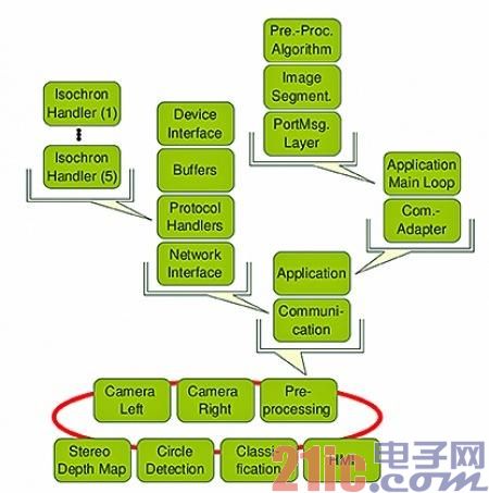
Figure 1: Modular structure of a virtual prototype
The distributed ADAS use case includes:
. Two cameras
. a preprocessor module
. a circumference detection module
. a speed marker classification module
. A stereo depth map calculation module
. a human machine interface (HMI)
The system includes two ADAS functions: Stereo Depth Map (SDM) and Traffic Sign Recognition (TSR). These two system functions share a common camera and image preprocessing module. The communication network must forward a number of different image streams, including the original captured image, the preprocessed image, the detected circumferential clip, the stereo depth map, or the classified velocity value. The requirements for the basic communication network are different depending on the role of the module. For example, the pre-processing module requires a communication combination of 1 to n to handle multiple receivers. The camera image stream provides a continuous stream of data. On the other hand, the clipped traffic signs appear in a sudden manner. In order to reveal the impact of this communication technology, it is necessary to analyze the camera data stream of the stereo depth map application in detail. The impact of communication technology on applications
The calculation of the stereo depth map requires simultaneous transmission of two preprocessed camera images. If the image is not associated with additional information such as a sequence number, then the receive buffer would necessarily contain a continuously synchronized camera image. Therefore, the communication network must ensure that the left and right camera images are always sent in pairs between two sequential read operations. Different kinds of communication networks may affect this behavior. There is a possibility of permutation due to, for example, a shared communication channel with uncertain access behavior. The use of different channel types or channels may result in different delays, which in turn leads to the use of older image instances.

Figure 2: Stereo depth map with displacement between left and right camera images (a) no replacement (b) one frame (c) two frames (d) three frame replacement
Figure 2 shows a stereo depth map when there are different permutations between the left and right camera images. Near objects appear as warm tones starting from red, and distant objects appear as cool tones, such as blue. The closer the object is, the warmer the color and vice versa. The upper left corner of the figure is the result image of the left and right image synchronization. It can be seen from the figure that the front tree (the right corner of the image) is well detected. In the image on the upper right, a frame replacement is introduced between the left and right cameras. The depth information does not cover the complete tree. In the image on the lower right, a three-frame permutation is inserted. As can be seen from the figure, the tree is barely detected, and the information about the distance is also different.
The MOST sync channel is the best channel for this task. It provides a non-shared channel with deterministic latency. Since it is a continuous stream of images, the bandwidth must be allocated. The biggest benefit of this channel is that it allows 1 to n communication, so both the pre-processing device and the HMI can receive the camera image and use the depth information to calculate the overlap.
Optimization of system parameters
The virtual prototype can be used to determine the optimal configuration parameters based on actual usage. The most important buffer in an ADAS application is between the MOST device and the application, as shown in Figure 1. The buffer is divided into receive and transmit buffers. The use of the receive buffer is used as an example. The MOST data processor simulating the basic behavior of the INIC extracts/writes data to the MOST frame from the MOST frame. The read data is stored into the receive buffer every 20.833?s. On the application side, the buffer is read at the application interrupt rate. In order to avoid buffer overflows and consequent data loss or retransmission, these read and write accesses must be balanced. In virtual prototyping, the use of buffers can be easily monitored, for example using different application interrupt rates, or various business scenarios that affect frame usage.
Evaluation of packet channel sharing applications
The great potential of virtual prototypes is the ability to analyze data services that depend on various parameters. The evaluation architecture allows data to be captured, monitored, compared, and analyzed at different nodes, such as data sent and received by applications, data processors, different types of buffers, or data on the MOST bus itself. Users can easily define data access points in a configuration file, allowing users to analyze the overall system behavior.
The following use case analyzes the behavior of two applications sharing a packet channel. In the case of TSR, the clipped image is transmitted over the packet channel because there is no need to use a fixed bandwidth allocation. This situation can evaluate the impact of additional connections. The first connection is based on the MOST High Protocol (MHP), and the second connection is based on the MOST Ethernet Protocol (MEP). TCP/IP.MHP is implemented by encapsulating the protocol originating from NetServices, and the TCP/IP protocol is adopted. Package open source lwIP - lightweight TCP / IP stack implementation.
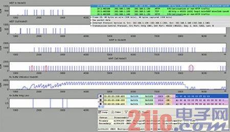
Figure 3: Evaluating TCP/IP and MHP Data Connections Using Different Tools
Figure 3 shows the extraction of trace data generated by a transmitter and a receiver. The bottom graph shows four buffer overflows in the shared receive buffer. The second-to-last graph shows the buffer usage in bytes. The middle two figures show data sent by, for example, circumference detection, (MHPOutNode01) and data received by, for example, the receiver HMI (MHPInNode00). It can be seen from the figure that two messages are lost due to buffer overflow (marked with a red circle in the figure), and the MHP retransmits the data at the end of the block. To verify the correctness of the behavior, the OptoLyzer tool suite can be used to additionally observe the MHP business trajectory. As shown, the MHP retransmits the 0x02 and 0x09 frames by sending a MultipleFramRequest.
The top two figures show the data exchange done by MEP communication. To analyze these communications, the open source packet analyzer Wireshark was used. In the submitted use case, it can be seen that the TCP/IP retransmission timeout (the frame loss triggered by the third buffer overflow) is long enough for the MHP connection to send. A complete data set. This simple example shows how to use the evaluation architecture to observe system behavior in detail. Complete integration of virtual prototyping methods can be achieved with links to existing analysis tools. Summary of this article
The above ADAS example shows that various system parameters must be determined during system design. The different examples above show that virtual prototypes can support a variety of decisions by providing simulation-based analysis to evaluate different alternatives. Virtual prototypes allow detailed observation of system behavior. With the help of existing analysis tools, you can analyze system behavior under different system constraints. In the TSR and SDM scenario analysis, many benefits of the MOST bus are used, such as the ability to transmit data concurrently on a unique synchronization channel and on a shared packet channel, using a transmitter or integrating additional communication protocols (such as TCP/) IP) The ability to address multiple receivers.
Mini Usb Vacuum Cleaner: This portable vacuum cleaner is very small (about 200mm) and very easy to take.
Rechargeable handheld cordless vacuum cleaner: This Mini Vacuum Cleaner can be used for cleaning hidden dirty of notebook keyboard, printer, pet food, office, kitchen table, or other small household appliances.
Car mini Usb Vacuum Cleaner: This USB vacuum cleaner can be used for cleaning car vent, dashboard, storage cabinet, sand, dust, paper, food debris, and so on.
Rechargeable wireless handy vacuum cleaner: this vacuum cleaner power supplied by usb port, which is very easy and convenient to use and store.
Easy to use: this mini vacuum cleaners` filter can be washed by water. Just open the dust pot and take it out, then wash it clean and use it again after it dry.
Mini Vacuum Cleaner
Keyboard Vacuum,Usb Vacuum,Mini Car Vacuum,Usb Vacuum Cleaner
SHENZHEN HONK ELECTRONIC CO., LTD , https://www.honktech.com