The MEMS-based system can significantly improve the alignment accuracy of the hip and knee joint implants with the patient's bone structure, reduce discomfort, and thus avoid corrective surgery.
Navigation is usually related to cars, trucks, airplanes, ships, and of course people. However, it has also begun to play an important role in the field of medical technology, and precision surgical instruments and robots need to use navigation. The design requirements of surgical navigation tools have a lot in common with traditional vehicle navigation, but the former also presents some unique challenges (for example, because it is used indoors and GPS support is not available), higher performance is required.
This article will study the unique challenges of medical navigation applications and explore possible solutions—from sensor mechanisms to system characteristics. First, we will review some important performance indicators of the sensor and the potential errors and drift mechanisms that should be considered in the sensor selection. This article will also focus on ways to enhance sensors through integration, fusion, and processing, such as through the use of Kalman filtering. However, before starting a detailed discussion, it may be helpful to review some basic principles of inertial microelectromechanical system (MEMS) sensor technology.
Basic principles of MEMS
MEMS technology, once thought to be whimsical, has now become a mature technology that most of us encounter every day. It makes our cars safer, enhances the usability of mobile phones, can measure and optimize the performance of tools and sports equipment, and continuously improves the level of medical care for inpatients and outpatients.

MEMS devices used for linear motion detection are usually based on a micromachined polysilicon surface structure, which is formed on a silicon wafer and suspended on the surface of the wafer by a polysilicon spring to provide resistance to acceleration forces. Under acceleration, the deflection of the MEMS axis is measured by a differential capacitor, which consists of an independent fixed plate and an active mass connection plate. In this way, the motion makes the differential capacitance unbalanced, causing the amplitude of the sensor output to be proportional to the acceleration. To give a familiar example, when a car suddenly decelerates suddenly and suddenly due to a collision, the MEMS shaft in the airbag sensor will produce the same motion, causing the capacitance to be unbalanced, and eventually generate a signal to trigger the airbag to open. This basic accelerometer structure can be adjusted according to different application performance parameters and added data processing functions, can accurately indicate the inclination, speed and even position. There is a different but technically related structure is a gyroscope, which can detect the rotation rate, the output format is degrees / second; accelerometer is to detect gravity.
Turn motion detection into information useful for healthcare
The ability to accurately detect and measure motion through a compact device with very low power consumption is valuable for almost any application involving motion, even for applications where motion requirements are not critical. Table 1 lists some basic medical applications by type of exercise. More advanced applications that need to solve more challenges will be discussed later.
Beyond simple motion detection
Although simple motion detection, such as linear motion on one axis, may be valuable, most applications involve multiple types of motion on multiple axes. Capturing this multi-dimensional motion state not only brings new benefits, but also maintains accuracy when off-axis disturbances may affect single-spindle motion measurement.
In many cases, in order to accurately determine the motion experienced by an object, multiple types of sensors (such as linear and rotary) must be combined. For example, accelerometers are sensitive to the gravity of the earth and can be used to determine the inclination. In other words, when a MEMS accelerometer is rotated in a gravitational field of ± 1g (± 90 °), it can convert the movement into an angular representation. However, accelerometers cannot distinguish between static acceleration (gravity) and dynamic acceleration. In this case, the accelerometer can be combined with the gyroscope, and the additional data processing capability of the combined device can be used to distinguish linear acceleration and tilt (that is, when the output of the gyroscope shows that the rotation and the apparent tilt recorded by the accelerometer coincide). As the dynamic degree of the system (the number of axes of motion and freedom of motion) increases, the sensor fusion process becomes more complicated.
It is also important to understand the impact of the environment on sensor accuracy. One obvious factor is temperature, which can be calibrated; in fact, high-precision sensors can be recalibrated and dynamically compensated for themselves. Another not-so-obvious consideration is potential vibration. Even slight vibrations can skew the accuracy of the rotation rate sensor. This effect is called the linear acceleration effect and vibration correction, and its effect may be serious, depending on Due to the quality of the gyroscope. In this case, sensor fusion can also improve performance, that is, use the accelerometer to detect linear acceleration, and then use this information and the gyro linear acceleration sensitivity calibration information to correct.
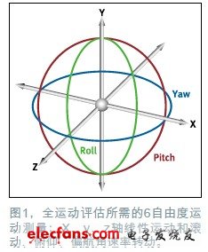
Many applications require multi-degree-of-freedom motion detection. For example, a 6-degree-of-freedom inertial sensor can simultaneously detect linear acceleration and rotational motion (also known as roll, pitch, and yaw) on the x, y, and z axes, see Figure 1.
Commercial Solar Led Parking Lot Lights systems manufactured by Bbier providing a great solution for parking lots and car park areas.Solar Powered Parking Lot Lights are great option for parking lot lighting as they are off grid and require no trenching. Greenshine New Energy offers the most cost-effective.Solar Parking Lights provide uncompromising optical performance and versatility.Solar matched with LED makes for the perfect mix of efficient Solar Park Lights .
Solar Led Parking Lot Lights
Solar Led Parking Lot Lights,Solar Powered Parking Lot Lights,Solar Parking Lights,Solar Park Lights
Shenzhen Bbier Lighting Co., Ltd , https://www.chinabbier.com